HVACR Systems 122: Load Calculations
122-2: Heat Loss of a StructurePage 7
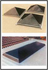 Worksheet C for Skylights
Worksheet C is used when the structure has skylights. If you have no skylights, simply leave this worksheet blank. Columns in the worksheet group the skylights by exposure direction. You will use one column for each type of skylight. Most homes with skylights will probably only have one or possibly two different types. The load area for these skylights is unique to each type. If you have duplicate skylights with the same attributes (see below) you will simply add the areas and put the total area in only one column.
 Identical skylight attributes include:
- Exposure direction and tilt angle
- Type of sash
- Number of panes (clear glass is the default)
- Curb size
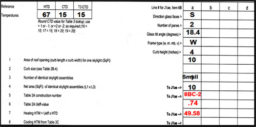 Example of Worksheet C partially completed
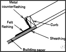

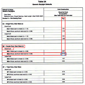
When completing Worksheet C, input data in the column(s) as necessary. When you get to Line No. 1, you will enter the area of the roof opening (skylight) which will be the curb length x the curb width in square feet (Sq. Ft. ). On Line No. 2 you will enter the curb size from Table 2B-4 in MJ8AE on page 106 (see below). This will equate to either small or large based on the area of the rough opening in square feet (Sq. Ft. ). Line No. 3 will be the number of identical skylight assemblies if you have a structure that has multiples of the same skylights. Line No. 4 will be the net area in square feet (Sq. Ft. ) of those identical skylights. (Simply Line No. 1 area x Line No. 3 number of identical skylights). Line No. 5 will be the Table 2A (see below) construction number for the particular type of skylight (an example is provided on this table). Line No. 6 will be the Ueff-value from Table 2A. Line No. 7 will be the Heating HTM (Ueff x HTD). The HTD comes from the top left of Worksheet C.
Table 2B-4
 |
 |
| Click to enlarge | |
Worksheet D for Opaque Panels
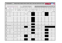
 Worksheet D is used to calculate heat loss (and gain) for opaque panels. For purposes of MJ8AE these are classified as the opaque surface of a wood or metal door, a wall, a ceiling or a floor.
First, transfer the values for HTD from Worksheet A to the top left corner of Worksheet D. We will discuss the similar cooling data in the cooling module later.
Under column 1 on the worksheet you will find Line 7 labeled with Wood and Metal Doors. Line 8 under column 1 is labeled Above Grade Walls followed lower on the form with Partition Walls. Line 9 is labeled Below Grade Walls. Line 10 is labeled Ceilings, followed lower on the form with Partition Ceilings. Line 11A is labeled Passive Floors, followed lower on the form with Partition Floors.
 |
| Click to enlarge |
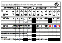
Worksheet D uses thirteen (13) columns for entering the construction number from Table 4A and the direction the door or wall faces (except for block loads), the length, the average height (or width), the gross area, the area of openings (windows, doors, etc. ), the net area (total wall area minus openings), exposed slab edge in feet (for slab floors), the U-value or slab F-value, the HTD, the heating HTM, the Group Number, the CLTD and the cooling HTM (cooling data will be discussed in 122-3). You will complete each column for the particular door, wall, ceiling, and floor. The values identified in columns 6, 7, 10, and 13 will be transferred to Form J1AE.
Column 6 is the Net Area (Sq. Ft. ) of the door, wall, ceiling, or floor. Column 7 is the Exposed Slab Edge (Ft. ) if you have a slab-on-grade. Column 10 is the Heating Heat Transfer Multiplier (HTM) calculated from multiplying the U-value or Slab F-value by the Heating Temperature Difference (HTD). Column 13 is the Cooling Heat Transfer Multiplier (HTM) calculated from multiplying the U-value or Slab F-value by the Cooling Load Temperature Difference (CLTD).
Most entries and calculations on Worksheet D are straightforward. Just use common sense and input the required factors. When you get to Column 5, remember that you are entering the area (Sq. Ft. ) of the openings in the panel. This means that for the doors, there is no adjustment if any glass area in the door is less than 50% of the door area (count all the area as door). If any glass area in the door is over 50%, delete the door from Worksheet D and add a French Door to Worksheet B. For walls, enter the area of the windows and doors associated with the wall (easier when walls are designated by direction).
Table 4A (When Calculating Heat Loss)
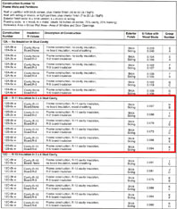
When completing Worksheet D you will need to refer to Table 4A. This will provide you with the construction numbers and U-Values necessary to calculate the Heat Loss HTM.
Heat Loss HTM = U-Value x (Indoor Design Temperature – Outdoor Design Temperature)
Heating Load (Btu/h) = HTM x Reference Area
The default indoor design temperature is assumed to be 70°F for most applications. The outdoor design temperature is provided from Table 1A. The reference areas are provided with the construction numbers. There are three (3) exceptions.
- Number 15 - Basement walls may be partly above and partly below grade
 Below Grade Heat Loss HTM = Below Grade U-Value x HTD
Heating Load (Btu/h) = HTM x Below Grade Wall Area
Above Grade Heat Loss HTM = Above Grade U-Value x HTD
Heating Load (Btu/h) = HTM x Net Above Grade Wall Area
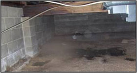 Number 19A - Passive floor over an enclosed crawl space
HTM = U-Value x Floor TD from Table 4A
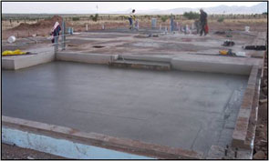
- Number 22 – Passive slab floor
HTM = F-Value x HTD (F-Value is transmission coefficient for ground slab heat loss)
Heating Load (Btu/h) = HTM x Running Feet of Exposed Edge
 |
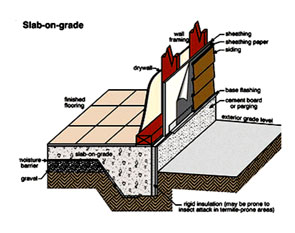 |
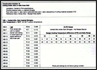
Table 4A has 17 pages of tables with U-values to help calculate the structure component heat loss. Heat loss can be significant depending on the component and 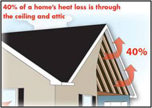 the circumstances. The tables include:
- Construction No. 11, Wood and Metal Doors
- Construction No. 12, Frame Walls and Partitions
- Construction No. 13, Block Walls and Partitions
- Construction No. 15, Basement Walls
- Construction No. 16, Ceiling Under Attic or Attic Knee Wall
- Construction No. 17, Ceiling on Exposed Beams
- Construction No. 18, Ceiling Below Roof Joists
- Construction No. 19, Floor Over Enclosed Unconditioned Crawl Space or Basement
- Construction No. 20, Floor Over Open Crawl Space or Garage
- Construction No. 21, Basement Floor
- Construction No. 22, Concrete Slab-On-Grade Floor
When using Table 4A and all its parts, you will locate the particular type of “Opaque Panel” that the heat is being lost through and utilize the U-value to enter into Worksheet D to calculate the Heating Heat Transfer Multiplier (HTM). You must determine the Heating HTM to determine the actual heat loss on Form J1AE.
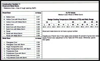
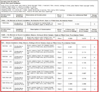
Below are Construction No. 11, (Wood and Metal Doors), Construction No. 12B, (R-11 Insulation in 2 x 4 Stud Cavity), Construction No. 13A, (Board Insulation Only, Stucco, Siding or Brick Veneer, Open Core, Plus Interior Finish), and Construction No. 16, (Ceiling Under Attic or Attic Knee Wall) to illustrate the configuration of the data. These particular sub-tables of Table 4A are used frequently when performing typical load calculations. All other data in Table 4A is in a similar format to those shown below. Additionally, there is a partially completed Worksheet D for an example house.
 |
 |
 |
 |
 |
|
| Click to enlarge above images | ||
Copyright © Blue C LLC. All rights reserved.