HVACR Systems 122: Load Calculations
122-2: Heat Loss of a StructurePage 11
Worksheet G, Lines 23 through 25
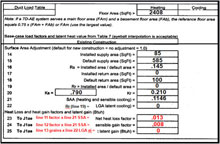
Lines 23 through 25 are used for the surface areas correction. This is the final step in the procedure and these values are exported to Form J1AE.
 |
| Click to enlarge |
Line 23 holds the effective heat loss factor for the duct system:
(Line 11 factor x Line 21 adj. factor)
Line 24 and Line 25 deal with cooling and will be discussed in 122-3.
Shown here is an example of this part of Worksheet G completed for an example house:
Worksheet H for Engineered Ventilation (for Heat Loss Calculations)
When infiltration occurs, it dilutes odors, gases and smoke, helps control indoor humidity levels during heating, and provides make-up air for exhaust fans and combustion air for gravity vented appliances (typically gas furnaces and gas water heaters).
 |
| Click to enlarge |
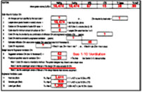
Worksheet H is used to calculate engineered ventilation loads. Bath and kitchen exhaust systems are not engineered ventilation systems.
Most of the time you will not utilize this worksheet as MJ8AE is customarily used for structures that typically require no engineered ventilation. But, if engineered ventilation is required, the structure will be so tight that the normal infiltration rate is unable to provide adequate comfort and indoor air quality. Worksheet H completed for an example residential structure is shown here:
 |
| Click to enlarge |
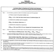
When working with Worksheet H, you will utilize Table 8A on page 145 in the MJ8AE Manual. This table is used to evaluate the need for engineered ventilation. The method involved simply compares the estimated infiltration rate with industry requirements for fresh air and combustion air, and suggests a design value for the ventilation rate (CFM).
Remember, local codes and standards always supersede Table 8A (shown here, but only used as guidance). In lieu of no local codes, you will have a professional and legal responsibility for the comfort, health and safety of the occupants and be solely responsible for decisions pertaining to the use of, and amount of, engineered ventilation.
If a local code does exist and specifies a fresh air requirement [an Air Change per Hour (ACH) value], don’t assume that normal infiltration will satisfy this need. Also, do not use the code ventilation ACH requirement as the input value for the infiltration ACH value.
If an unbalanced engineered ventilation system is installed in a residential structure, the pressure in the conditioned space will be greater or less than the outdoor ambient pressure and the infiltration rate will decrease or increase. Utilize the unabridged edition of Manual J if this situation occurs to address this issue and adjust the infiltration estimate for the pressure condition caused by the engineered ventilation system. If the kitchen is equipped with a powerful range hood (150 CFM or more); provide powered relief dampers. The operation of the range hood should not cause any combustion appliance to back-draft. Fireplace or wood stove operation should not cause combustion appliances to back-draft either. When a fireplace or wood stove draws combustion air from a conditioned space, you should provide powered makeup air, open windows, or a pressure relief damper in the system(s).
Room by Room Load Estimates
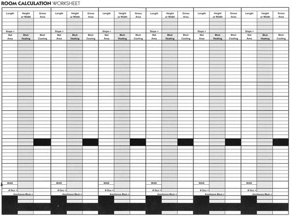
Form J1AE is used for calculating room loads for both heat loss and heat gain (discussed in 122-3). It is very similar to the block load procedure with the exception that Lines 1 through 5 are used for room loads, that each room has a unique gross Wall Area Ratio (WAR), that there is no latent gain for rooms, and that there is no system load for rooms. We will utilize the room by room method to complete a heating and cooling load calculation for an example residential structure in 122-4.

Copyright © Blue C LLC. All rights reserved.