HVACR Systems 122: Load Calculations
122-3: Heat Gain of a StructurePage 5
Order of Progression for MJ8AE
When you use the MJ8AE method for calculating heat gain, you will be following a process using the forms associated with MJ8AE. The normal progression is as follows:
| Worksheet A: | Design conditions |
| Worksheet B - C: | Window, glass doors & sky light loads |
| Worksheet D: | Opaque surface loads |
| Worksheet E: | Infiltration loads |
| Worksheet F: | Internal loads is not used in MJ8AE |
| Worksheet G: | Duct loads |
| Worksheet H: | Ventilation loads |
| Form J1AE: | Room load estimates |
We will complete all of the above forms applicable when we perform a load calculation in 122-4. On occasion, you may not have to complete some of them.
Survey
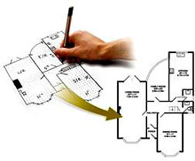
 You must begin any calculation with the survey. You may also create your own. Using a survey form will involve gathering data for the structure. You will estimate the cooling load based on the conditions that currently exist or that will exist at the site. If you are checking an existing structure the survey information is obtained from an on-site inspection and talking to the owner or builder. For new or proposed construction, the survey information is obtained from drawings, plans, and specifications, and from talking to the builder, architect or owner.
When you have to complete an on-site inspection you will be taking measurements of the structure and detailed information concerning the thermal efficiency of the structure components, internal loads and infiltration. It is assumed that you understand how to measure and are familiar with formulas for area, area of a triangle, circles and volume. Other measurements may also be required.
The location of the dwelling, as previously discussed, is determined by selecting the nearest city or town that is listed in Table 1A. This table determines the outdoor design conditions for heat gain calculations (in this instance). It will also determine outdoor design conditions for heat loss calculations (discussed in 122-1).
Heat gain calculations depend on the dimensions of the structural components. The heat gain associated with ceilings, walls, windows, doors, and exposed floors is proportional to the surface area of the component (panel). The heat gain associated with a slab floor, a conditioned basement, or a below grade wall are considered as zero for cooling, as the earth is cooler than the structure and no heat gain is produced. The volume of the cooled space is used to convert infiltration air-change values to infiltration CFM values.
Worksheet A (Design Conditions)
Worksheet A provides a record of the indoor and outdoor design conditions for the structure that are utilized during the heat gain calculations.
You will (as previously discussed) look in Table 1A for the location of the dwelling to determine the outdoor design conditions used for the MJ8AE heat gain calculations. It is listed under the heading “Summer, Cooling 1% Dry Bulb.”
We complete Worksheet A and then transfer the necessary information to Worksheet: Form J1AE per the following:
-
Project (Name) and Location
Click to enlarge - Indoor design temperature - heating and cooling
- Indoor humidity (RH value) for heating and cooling
- Elevation and latitude
- Outdoor design temperature for heating
- Outdoor design temperature for cooling (1% value)
- Grains difference value for cooling (for specified indoor RH value)
- Daily range classification
- Design value for heating temperature difference (HTD)
- Design value for cooling temperature difference (CTD)
- Design value for altitude correction factor (ACF)
Fenestration
 When you are calculating heat gain through windows, glass doors, and skylights the answer will equal the product of the cooling HTM value and the load area in square feet. You must measure the actual openings or review plans (if available). These openings are often referred to as “Fenestration.” Technically, fenestration is described as any transparent or translucent material plus any sash, frame, mullion or divider. This includes windows, sliding glass doors, French doors, skylights, curtain walls and garden windows.
Default HTM values for generic fenestration are provided by Tables 3A and 3C of MJ8AE. These values will not work effectively for windows, glass doors and skylights rated by the National Fenestration Rating Council (NFRC). They also will not work for the following: generic glazing other than clear glass, glass blocks, generic windows or glass doors equipped with external sunscreens, dome skylights, or skylights sensitive to curb construction, or equipped with light shafts.
If any of these situations exist with the windows and/or glass doors being found in the structure you are calculating the heat gain for, you should use the unabridged version of Manual J.
Tables 3A and/or 3C provide unadjusted HTMs for windows, glass doors and skylights.
Table 3A and Table 3C are shown and referenced later in this module.
No adjustment is necessary for skylight HTM values.
For windows and glass doors, the shade by overhang adjustment is applied to all vertical openings where the overhang is effective. North facing glass is considered to have “no effect.” Table 3E-1 (shown later in this module) on page 109 of the MJ8AE Manual is used to adjust values due to shade by overhang.
The adjusted HTM must be readjusted for projected construction or for an insect screen. After the adjustments, the sensible gain is found by multiplying the adjusted HTM value by the load area.
When dealing with windows and glass doors, the following assumptions when using MJ8AE apply:
- Purpose-built daylight windows and skylights are assumed to have no internal shade
- All other windows and glass doors shall have internal shade
- The default assumption for internal shade is a medium-color blind with the slats at 45 degrees
- An overhang adjustment shall be applied to all windows and glass doors
- When available, you should use the actual overhang geometry or use the default geometry
- The default length of the overhang is one foot; the default height above the glazing is one foot
- The heat gain adjustment for any type of insect screen shall be 0.90
- The heat gain (and loss) adjustment for a bay window shall be 1.15
- The heat gain (and loss) adjustment for a garden window shall be 2.75 (and 2.00)
- The heat gain adjustment for a French door shall be 0.70
When dealing with skylights, the following assumptions when using MJ8AE apply:
- Curb construction shall default to (un-insulated) wood 2 x 4; four inches high
- Skylights shall not be equipped with an internal shade or light shaft
 |
| Click to enlarge |
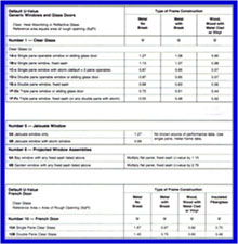
Table 2A (see insert) on pages 103 - 105 of the MJ8AE Manual has six (6) individual tables within it, comprising: Clear Glass, Jalousie Windows, Projected Window Assemblies, French Doors, and Generic Skylights (single pane, double pane, and triple pane). You simply select the type of glass opening from these tables and use the appropriate information.
Heat Gain from Fenestration
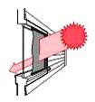
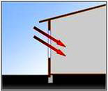
The HTM for heat gain of an unshaded opening (window or glass door) depends on the combined effect of the solar radiation passing through the glass (Solar Component = HTMs) and the heat conducted through the glass, sash and frame (Conduction Component = HTMc).
Heat transfer through glass exercise
The Solar Component is the primary source of summer fenestration gain (except  for North glass).
Fenestration HTM = HTMs + HTMc
Refresher - Addition of Decimals
Solar Component
To effectively produce HTM values to include the “Solar Component,” you must consider the following:
- The Peak Solar Factor (PSF) is the incident radiation that strikes the glazing assembly of a glass window or door
- The Cooling Load Factor (CLF) is a thermal storage factor
- The Solar Heat Gain Coefficient (SHGC) ÷ 0.87 = the shading coefficient of an unshaded glazing assembly
- The Internal Shading Coefficient (ISC) is the internal shade factor
So we get the formula:
HTMs = PSF x CLF x SHGC/0.87 x ISC
Tables in the unabridged version of Manual J provide values for PSF, CLF, ISC, and SHGC for generic fenestration.
Copyright © Blue C LLC. All rights reserved.