HVACR Systems 122: Load Calculations
122-4: Example Heat Loss and Heat Gain CalculationPage 10
Worksheet H for Engineered Ventilation (for Heat Gain Calculations)
Worksheet H is used to calculate engineered ventilation loads. Bath and kitchen exhaust systems are not engineered ventilation systems. Most of the time we will not utilize this worksheet as MJ8AE is customarily used for structures that typically require no engineered ventilation. We will assume 50 CFM ventilation. But, if engineered ventilation is required, the structure will be so tight that the normal infiltration rate is unable to provide adequate comfort and indoor air quality. When working with Worksheet H, you will utilize Table 8A on page 145 in the MJ8AE Manual. This table is used to evaluate the need for engineered ventilation. The method involved simply compares the estimated infiltration rate with industry requirements for fresh air and combustion air, and suggests a design value for the ventilation rate (CFM).
Block Load Calculation (Estimate)
 |
| Click to enlarge |
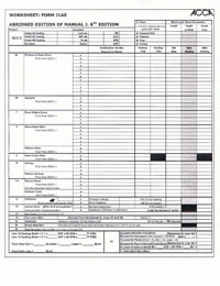
MJ8AE allows you to estimate the Block Load of the structure first on Form J1AE. The first 21 lines on the form are used for this calculation. First, you must transfer the indoor and outdoor design conditions from Worksheet A to the upper left corner of Form J1AE. Next, you simply proceed down the form from line 6A to line 21. (Lines 1 through 5 are used for room by room calculations, not for the block load estimate. ) Since we know the total square footage of our example house is 1,479 Ft², we will utilize this value to calculate the block loads. You may often have to measure the outside dimensions of the house if this value is not available. We have modified this block load form to allow for ease of completion. You may print this form for your use as necessary.
Columns
There are six (6) input columns for each line item. Begin with the left column and work to the right.
“Column 1” is titled “Construction Number – Direction & Details”. Enter the Construction numbers we have identified for the load calculations in each area down the page (glass, skylights, doors, etc. ). For example, enter the direction glass faces, and any text or code that links the line item to a particular room. You can also enter the total area in square feet for the particular line item since we are estimating the block load. When you get to Line 12, you will enter infiltration information from Worksheet E. Line 13 is for internal gains. Line 14 is for sub-totals. Line 15 is for duct loss/gain. Line 16 is for any ventilation. Line 19 is for blower heat gain. Line 20 is for total sensible loss or gain for the block load. Line/Area 21 is for latent infiltration gain and latent loads.
“Columns 2 and 3” are where you enter the Heat Transfer Multipliers for Heating and Cooling that you have either selected from the MJ8AE Manual or calculated from a worksheet.
“Column 4” is for Net Area. Simply transfer the net area of windows and glass doors from Worksheet B, Line 11 as necessary. Doors, walls (minus glass), ceilings, and floors will also have net areas in this column. You will also need to calculate the Gross exterior wall area (length x height) and then subtract the total glass areas in the walls from that value to get the net wall area.
Now you will multiply the Column 2 Heating HTM by the Column 4 area and enter the Btu/h heat loss value in Column 5 all the way down the page for each line item. Then you multiply the Column 3 Cooling HTM by the Column 4 area and enter the Btu/h heat gain value in Column 5 for each line.
Sections/Lines
Section/Line 6A is for Windows and Glass Doors (vertical glass). Note that the columns on Worksheet B map to line items on Form J1AE (the number of lines on Form J1AE equal the number of active columns on Worksheet B).
Section/Line 6B is used for skylights. Worksheet C columns will map to the line items on Form J1AE. Of course, we do not have skylights in our example house so this section will be left blank.
Lines 7 through 11 are used for wood and metal doors, above grade walls, below grade walls, ceilings, and passive floors. Use a new line (a, b, c, etc. ) for each different type of construction as necessary. Since we have only one type of each of these exposures for our example house, our inputs will be relatively simple.
Line 12 is used to evaluate the infiltration loads for our example house. We will enter the square feet of gross exposed wall area (used to calculate wall area ratio values for room infiltration estimates). We will enter the envelope tightness classification and the number of fireplaces. We will enter the infiltration CFM for heating and cooling from Worksheet E. And, we will enter the Btu/h loss and gain for infiltration (from lines 10 and 11 on Worksheet E).
Line 13 is used to evaluate internal gains. We will enter the number of bedrooms and the number of occupants for our example house (the default value is the number of bedrooms plus one) to calculate the 230 sensible gain per person for Line 13a. We enter 1,200 Btu/h or 2,400 Btu/h for the sensible appliance gain on Line 13b.
Line 14 is for the values for the total infiltration load. We will add the heating loads on Lines 6A through Line 13 and enter the sum on Line 14. We will add the sensible gain loads on Lines 6A through Line 13 and enter the sum on Line 14 as well.
Line 15 is for the duct loads. We will enter the applicable heat loss and gain factors from Worksheet G, Lines 23 and 24, and multiply the Line 14 heat loss value by the heat loss factor and enter the Btu/h value on Line 15. Then we will multiply the Line 14 heat gain value by the heat gain factor and enter the Btu/h value on Line 15.
Line 16 is used for engineered ventilation and will require that we enter the value for fresh air CFM used for the example house from Worksheet H, Line 10. We will also enter the Btu/h for the heat loss and heat gain from Worksheet H, Lines 11 and 12. As we assume 50 CFM or less as MJ8AE recommends, and that you are not utilizing Worksheet H, the simplest process is to perform the following calculations using the equations provided and enter the results as indicated:
1.1 x ACF x CFM x HTD
(1.1 x 0.96 x 50 x 66) = 3,485 Btu/h (insert on Line 16, under Btu/h Heating column)
1.1 x ACF x CFM x CTD
(1.1 x 0.96 x 50 x 22) = 1,162 Btu/h (insert on Line 16, under Btu/h Cooling column)
0.68 x ACF x CFM x Grains
(0.68 x 0.96 x 50 x 21) = 685 Btu/h (insert on Line 21e, under Btu/h Cooling column)
Lines 17 and 18 are used if winter humidification and hot water piping loss are necessary. These lines do not appear on Form J1AE because they are not applicable to MJ8AE.
Line 19 is for blower heat gain. Enter 1,707 Btu/h in the cell if the manufacturer’s performance data does not adjust the sensible capacity of the cooling equipment for the effect of the blower heat. If it does, enter 0 in the cell. We will assume that the equipment does include the effect of blower heat. You can also refer to Table 11, Blower Motor Heat for more information.
Line 20 is for equipment sizing loads. Add the heating load values on Line 14, Line 15, and Line 16 and enter the sum on Line 20. Add the sensible gain values on Line 14, Line 15, Line 16, and Line 19 and enter the sum on Line 20.
Section/Line 21 (a through f) is used for the latent equipment sizing load:
- Line 21a is for latent infiltration (Btu/h) for cooling from Worksheet E, Line 12
- Line 21b is for latent gain (Btu/h) for occupants (200 x the number of occupants)
- Line 21c is for latent gain (Btu/h) for plants (10 x the number of small + 20 x the number of medium + 30 x the number of large) We will assume 5 small and 5 large = 200 Btu/h
- Line 21d is for latent gain (Btu/h) for ducts located in unconditioned spaces from Worksheet G, Line 25
- Line 21e is for latent gain (Btu/h) for engineered ventilation from Worksheet H, Line 13
- Line 21f is for Total latent gain (Btu/h) equaling the sum of Lines 21a through Line 21e
 |
| Click to enlarge |
Completed Block Load for Example House
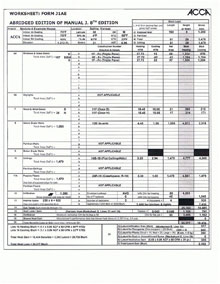
We have completed the explanation of the entries and calculations for the block load. The result is provided here for reference. Remember, we will use this information when calculating room by room loads. Also remember that all areas and HTMs come from previously completed worksheets.
Explanations and Links to View Sources for the Module 4 Example House
 |
|---|
| Click to enlarge |
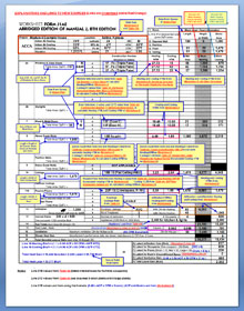
We have also provided you with a completed block load for the Example House that includes explanations and links to sources for your use. This will allow you to simply click on the particular link and go immediately to the worksheet or page that contains the necessary information used to complete the block load. This should assist you in understanding the actual sources for the information and the steps necessary for any load calculation using MJ8AE. The sources of information will be the same when you perform room by room calculations for the same structure.
Room by Room Calculations for the Example House
The Form J1AE procedure for room load calculations is very similar to the block load procedure. The only significant difference is that lines 1 through 5 are used for room loads, that each room has a unique gross wall area ratio (WAR), that there is no latent gain for each room (latent gain is added after the sensible loads are determined for all the rooms from the totals mentioned for Line 21), and that there is no system load for individual rooms (Lines 16 and 19 are not used).
 |
| Click to enlarge |
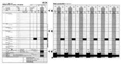
When performing room load estimates, you can simply unfold the Room Calculation Worksheet and match the left side arrows with the Form J1AE right side arrows. This provides you with the necessary Heating and Cooling HTMs necessary to calculate the room loads. This arrangement is shown here:
Line 1 is used to identify the location of interest. Enter the name of the room served by the unit.
Line 2 is where you will enter the running feet (length) of the wall exposed to the outdoors (or an attached unconditioned garage). You also will enter the average wall height and the gross wall area. As we have only one type of exposed wall for our example house, the gross area can be used for the Line 8 calculations. If we had more wall types, we simply use a scratch sheet to produce values for the Line 8 wall areas. (The total length of the Line 8 walls should equal the Line 2 length).
Line 3 is used to enter the running feet of any partition wall, the average height and the gross wall area.
Line 4 is where you will enter the room length, the room width and the corresponding floor area.
Line 5 is for the ceiling slope (degrees from horizontal) and the gross ceiling area. If the ceiling is horizontal, the ceiling area equals the floor area. If the ceiling slopes, the ceiling area equals the floor area divided by the cosine of the slope angle (see Table A4-1 in Appendix 4, Section A4-1 of the MJ8AE Manual.
Line 6A and Line 6B: Enter the load area (Sq. Ft. ) for each type of window, glass door and skylight; and be sure to place these entries on the lines (a, b, c, etc. ) that have the appropriate attributes (construction number, location, type of internal shade, exposure direction, height and width) as listed at the left of Form J1AE.
Then multiply the load areas by the corresponding heating and cooling HTM values to obtain the values for the heating and cooling loads (Btu/h), and then enter these load values in the appropriate cells.
Line 7 through Line 11: Enter the load area (Sq. Ft. ) for wood and metal doors (gross area), above grade walls (net area), below grade walls (gross area), ceilings (net area) and floors (gross area or slab perimeter); and be sure to place these entries on the lines (a, b, c, etc. ) that have the appropriate attributes (construction number, location, length, height or width; as listed at the left side of Form J1AE. Then multiply the load areas by the corresponding heating and cooling HTMvalues to obtain values for the heating and cooling loads (Btu/h); and then enter these load values in the appropriate cells.
Line 12: Calculate the gross exposed wall area for the particular room. Divide this area by the gross exposed wall area for all the rooms served by the central equipment to obtain the wall area ratio (WAR value) for the room. Enter the WAR value for the room by the block infiltration loads (heat loss and sensible gain) to obtain room infiltration loads (Btu/h) for the heating and cooling; and then enter these load values in the appropriate cells.
Line 13: Assign portions of the total (sensible) cooling loads for the room; then enter these load values in the appropriate cells.
Line 14: Sum the heating loads and sensible cooling loads for the room, then enter these load values in the appropriate cells.
Line 15: Multiply the room heat loss and the room sensible gain by the duct heat loss and the duct sensible gain factor; then enter these load values in the appropriate cells. No duct load equals 0.
Line 20: Sum the Line 14 and Line 15 loads and enter the sum on Line 20.
Copyright © Blue C LLC. All rights reserved.