


 20 / 156

Page 8
Chapter 1: What Is Electricity?
Electrical Theory & Applications for HVACR
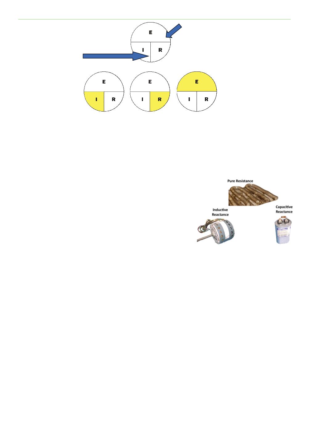
RESISTANCE AND REACTANCE
There are three important types of opposiƟon to electron flow: pure resistance, inducƟve reactance,
and capaciƟve reactance.
PURE RESISTANCE
Pure resistance is opposiƟon to current flow where the current
stays in phase with the voltage. Pure resistance can be directly
measured with an ohm meter and will only change with
temperature. Toasters and electric heaters are examples of
loads that have close to pure resistance. (Ohms Law: With a
fixed resistance, higher voltage increases amperage and lower
voltage decreases amperage.)
INDUCTIVE REACTANCE
When a conductor is wound into a coil, the magneƟc lines of force overlap and reinforce each other
inducing a counter‐EMF or opposing alternaƟng current in the adjacent windings. The counter‐EMF is
the source of opposiƟon to current flow. A constant direct current has a zero rate‐of‐change and sees
an inductor as a short circuit (it is typically made from a material with a low resisƟvity). An alternaƟng
current has a Ɵme‐averaged rate‐of‐change proporƟonal to frequency; this causes the increase in
inducƟve reactance with frequency is referred to as impedance. The formula for inducƟve reactance
is:
XL = 2 π (3.14) x (f) frequency x (L) Inductance in Henrys
The inducƟve coil has a low measured resistance unƟl it is energized and increases in impedance
during operaƟon, due to reactance. Transformers, solenoid coils, and motor windings are examples
of components that produce inducƟve reactance. These devices produce a magneƟc field and voltage
of their own in direct opposiƟon to the supply voltage. This counter‐EMF acts like an addiƟonal
resistance impeding current flow and is created only when the device is operaƟng. Counter‐EMF
decreases current flow aŌer start‐up and during operaƟon of the device. (Ohms Law: increased
resistance decreases amperage, and lower resistance increases amperage.)
Fig. 1‐8: Types of Resistance
Indicates MulƟply
Indicates Divide
Fig. 1‐7: Cover the unknown item and follow the instrucƟons
indicated by the horizontal or verƟcal lines.