


 99 / 156

Electrical Theory & Applications for HVACR
©2012 ESCO Group
Student Worksheet
Page 87
Chapter 4: Understanding Wiring Diagrams
Name _______________________________
Date _____________________
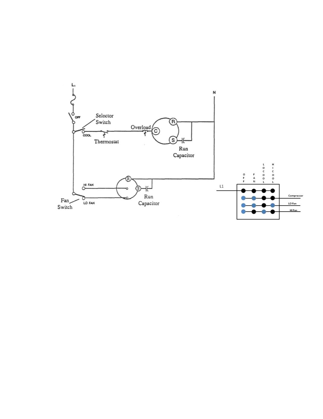
Typical 120 volt window air condiƟoner wiring schemaƟc. Both motors are PSC’s and the compressor
requires a 3 to 5 minute delay before restarƟng.
Black dots indicate electrical connecƟons for switch posiƟon to L1.
Blue dots indicate no electrical connecƟon to L1
.
For each problem all electrical components are to be checked for defects:
1. With the system turned on, only the high speed fan runs.
2. Fan motor runs on either speed, but compressor does not run.
3. Fuse is good , but compressor and fan will not run.
4. On low cool, only the compressor runs.
5. On high cool, only the fan motor runs.