


 96 / 156

Page 84
Chapter 4: Understanding Wiring Diagrams
Electrical Theory & Applications for HVACR
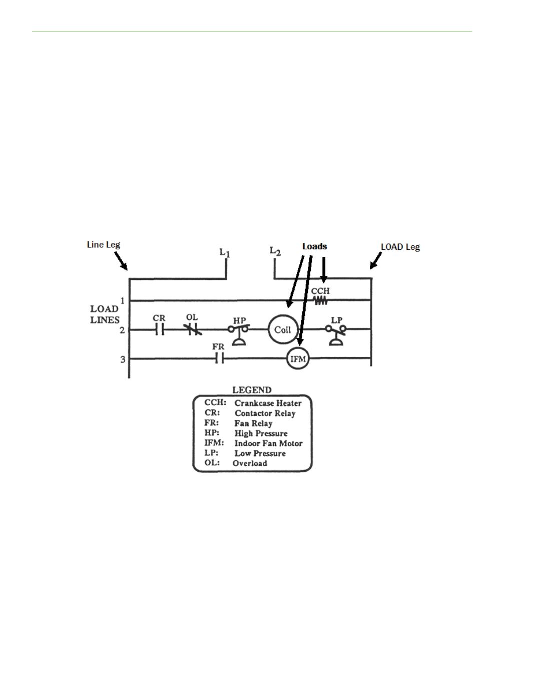
LADDER DIAGRAMS
Another type of diagram is the ladder diagram. A ladder diagram (Figure 4‐6) is arranged with the
power supply lines drawn verƟcal as the legs of a ladder. Each horizontal line, or rung of the ladder,
contains one load and its control switches. The load lines may be numbered for ease of idenƟficaƟon.
Control switches are usually located on the line side of the device being controlled; however, some
manufacturers place a switch or two on the load side of the rung.
Note:
Contacts and switches are always shown in the de‐energized posiƟon on most diagrams, there
are Ɵmes where the contacts on switches are shown based on equipment operaƟng cycle (example:
ice machine harvest cycle).
To use a schemaƟc or ladder diagram, a technician must have knowledge of equipment components
and their corresponding electrical symbols. Most schemaƟc diagrams contain a legend that lists any
abbreviaƟons and special components, as shown in Figure 4‐6.
Fig. 4‐6: Ladder diagram