


 93 / 156

Electrical Theory & Applications for HVACR
Chapter 4: Understanding Wiring Diagrams
Page 81
Understanding Wiring Diagrams
4
PICTORIAL AND SCHEMATIC DIAGRAMS
A wiring diagram is a simplified pictorial representaƟon of an electrical circuit. Different types of
diagrams have different applicaƟons in the HVACR industry. For example, installaƟon diagrams are
used by installers in making electrical connecƟons for high and low voltages, but are not useful for
technicians trying to troubleshoot equipment. Pictorial diagrams readily idenƟfy components and the
wiring between them in detailed physical appearance and are used for locaƟng electrical
components, line connecƟons, and wire colors, and for troubleshooƟng. Pictorials show how
components and switches are actually wired, making simple circuits easy to understand. When many
electrical components are involved, however, a pictorial diagram becomes too cumbersome to be
used for tracing circuits or troubleshooƟng.
A schemaƟc does not illustrate where components are located, but how they are connected in the
circuit. SchemaƟcs are less cluƩered than pictorials; they present the sequence of operaƟon in an
organized manner and use symbols to illustrate components. Experienced technicians prefer
schemaƟcs because they make circuits easily traceable, facilitaƟng troubleshooƟng.
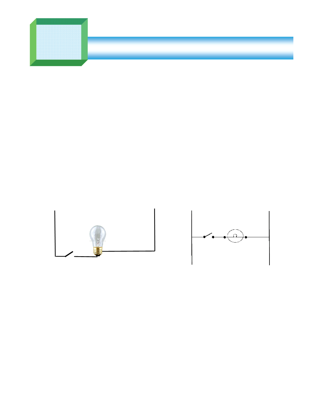
Pictorials Versus Schematics
Pictorial drawings show components and wiring as they actually appear, whereas schemaƟcs use
symbols to represent components and may not show specific locaƟons. Figures 4‐3 (a and b) each
show a circuit represented by both a pictorial and a schemaƟc diagram.
Combining Pictorial and Schematic Drawing
Figure 4‐4 is a diagram for a Frigidaire© side‐by‐side refrigerator/freezer. It shows both a pictorial
diagram for locaƟng electrical components and a schemaƟc diagram to clearly illustrate the various
electrical circuits. Dual diagrams like this one are very useful when troubleshooƟng equipment with
concealed wiring.
Hot
Neutral
Switch
Load
Fig. 4‐1: Pictorial diagram
L1
N
SPST
Light
Fig. 4‐2: SchemaƟc diagram