


 120 / 156

Page 108
Chapter 6: Troubleshooting
Electrical Theory & Applications for HVACR
VOLTMETERS
A voltmeter measures the potenƟal difference between any two points, much like a pressure gauge
indicates pressure difference.
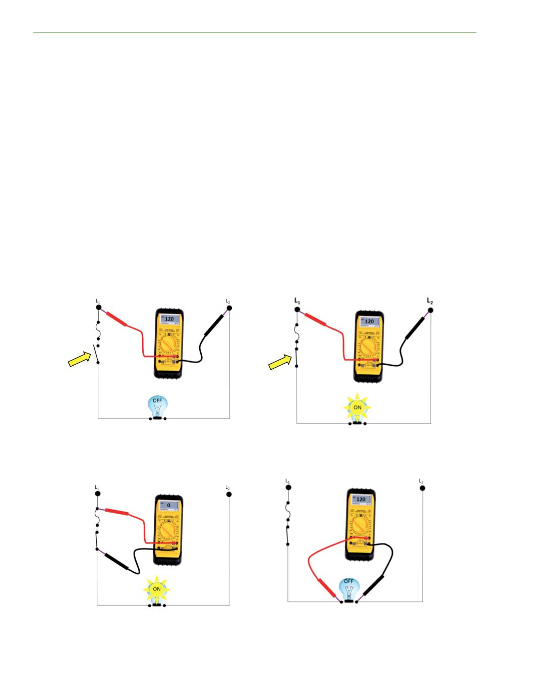
In the circuit shown in Figure 6‐1(a), a measurement of 120V should be obtained if the voltmeter
leads are placed between L1 and N. This shows that there is potenƟal between the two measured
points. However, the power‐using device (the light bulb) is not operaƟng because the switch is open.
In Figure 6‐1(b), the voltmeter leads are sƟll measuring the potenƟal between L1 and N, but the
power‐using device is on.
Figure 6‐1(c) illustrates that switches and fuses do not, or at least should not, use power. The
potenƟal between the two measured points is exactly the same, so there is no voltage measurement
on the meter. If the contacts in the switch were corroded, the resistance would cause power
consumpƟon (heat) and a reading on the voltmeter. When a voltmeter is placed across a switch, any
reading above 0.02 volts in a 120‐volt circuit may indicate a failed component.
In Figure 6‐1(d), the voltmeter leads are sƟll measuring the potenƟal between L1 and N, but the
power‐using device is burned open.
Fig. 6‐1(a)
Fig. 6‐1(b)
Fig. 6‐1(c)
Fig. 6‐1(d)