


 126 / 156

Page 114
Chapter 6: Troubleshooting
Electrical Theory & Applications for HVACR
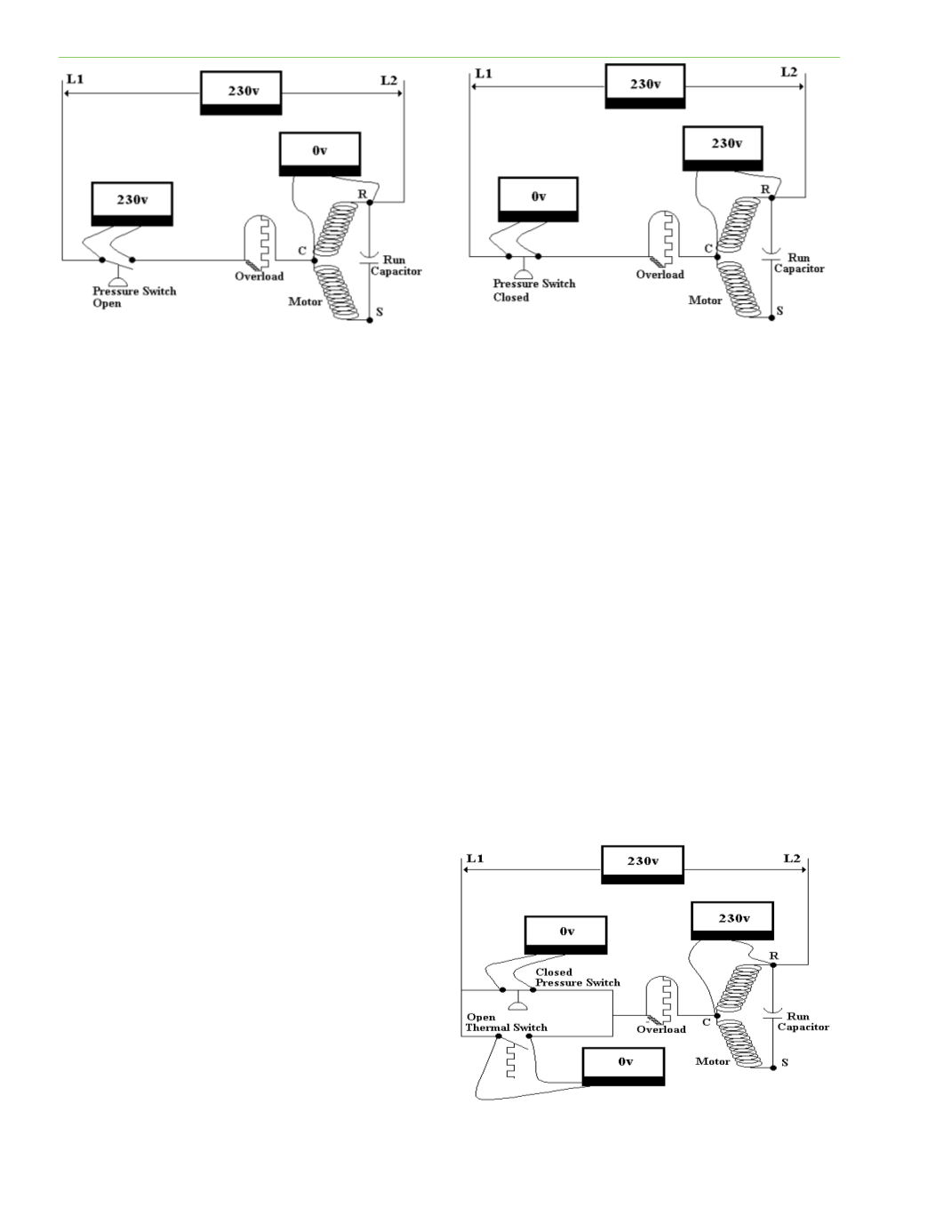
of a voltmeter were placed between Line 1 and Line 2, the meter would read 230 volts. If a technician
measured the voltage across the open switch, a voltage of 230 volts would also be read on the
voltmeter. This happens because Line 1 ends at the leŌ side of the open switch, and Line 2 simply
bleeds through the run winding of the motor, through the closed overload, and ends at the right side
of the switch. Since the motor is not running or consuming power, then the windings are nothing but
conducƟve wire for Line 2 to bleed through. If a technician were to measure the voltage across the
run winding (between R and C) of the PSC motor, the voltage would be 0 volts because the motor
winding is simply passing Line 2 when it is not running. Line 2 would be at both the R and C terminals
of the motor, and the potenƟal difference or voltage difference between Line 2 and Line 2 is 0 volts.
However, if the technician references either the R or C terminal to the ground, the voltage would be
115 volts.
In Figure 6‐11, the switch is closed and the motor is running. The motor is now consuming power and
will drop the enƟre line voltage of 230 volts across its run winding (terminals R and C) while it is
running. If the technician measures voltage across terminals R and C of the motor, 230 volts will be
measured. A voltage measurement across the closed switch will read 0 volts. This is because Line 1
ends at the C terminal of the motor it is running. The switch experiences Line 1 at both its terminals,
and the potenƟal difference or voltage difference between Line 1 and Line 1 is 0 volts. If a technician
measures from one terminal of the switch to the ground, the voltage reading will be 115 volts.
In the previous examples with switches and
motors, the voltmeter across the open switch
reads 230 volts, while the closed switch reads 0
volts. If one concluded that open switches
always read voltage and closed switches
always read 0 voltage, that would be wrong.
The next example will clarify this concept.
Figure 6‐12 shows two switches in parallel, but
at the same Ɵme in series with a motor (power
consuming device). The top switch is closed,
Fig. 6‐10
Fig. 6‐11
Fig. 6‐12