


 130 / 156

Page 118
Chapter 6: Troubleshooting
Electrical Theory & Applications for HVACR
Locked Rotor Amps (LRA)? This is before the overload had opened. Figure 6‐15 illustrates this
scenario. NoƟce that a voltmeter placed across the R ‐and C terminals of the motor (the opened
winding) will again read 230 volts. In fact, all the voltages in Figure 6‐15 and Figure 6‐16 are the
same. Figure 6‐16 illustrates that whether the motor is running properly or if it has an open winding,
the voltage will sƟll read 230 volts across R and C. So how does the service technician determine if
the run winding is open or not? The answer is with an ohmmeter.
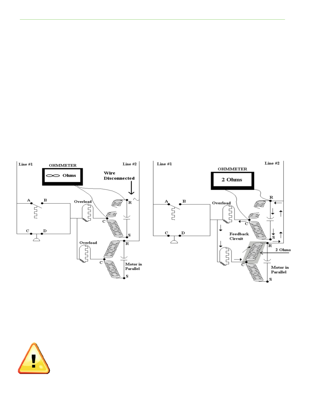
The service technician must shut down and disconnect one wire, either from the R or C terminal of
the motor (Figure 6‐17). DisconnecƟng the wire will prevent electrical parallel feedback from the
ohmmeter’s internal voltage source through another parallel electrical circuit. The technician must
then place an ohmmeter across the R and C terminals of the motor. The measurement will read
“infinite ohms” if the winding is open. This is the only way the service technician can tell if the
winding is open or not.
Figure 6‐18 shows a parallel feedback circuit from the ohmmeter’s internal voltage source if a wire
was not disconnected from the motor terminals. In this case, the ohmmeter reading would be 2
ohms. This could fool the technician into thinking the winding was sƟll good.
TESTING CAPACITORS
Capacitors (run or start) can be tested and the actual capacitance found using a capacitor tester found
on most digital meters. An ohmmeter can be used to check basic condiƟons of a capacitor, such as a
shorted or open circuit and whether or not the plates will take a charge.
When tesƟng a capacitor with an ohmmeter, the capacitor must first be discharged in
order to prevent damage to the capacitor or ohm meter. Do not short across the
terminals with a screwdriver; the proper method is to use a 15,000 ohm, two waƩ
resistor connected across the capacitor terminals. This will allow the current to dissipate
slowly and avoid damaging the capacitor.
Fig. 6‐18
Fig. 6‐17