


 125 / 156

Electrical Theory & Applications for HVACR
Chapter 6: Troubleshooting
Page 113
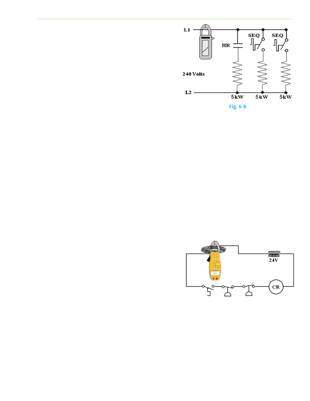
When the circuit is energized, the first element should
measure approximately 20.8 amps. As the sequence
Ɵmer energizes the second element, the reading should
increase to approximately 42 amps. When the third
element is energized, the current should increase to
approximately 63 amps.
A voltmeter can be used to check the voltage applied to
each element, but will not indicate whether the
element is funcƟoning.
An Ohmmeter can be used, with the power
disconnected, to check the resistance of each element
to ensure that none are open, but this is very Ɵme
consuming.
An ammeter check is a much quicker way of finding out if each element is operaƟng. It shows us
whether there is voltage to the load, current flow, and a complete circuit.
When measuring small amounts of current, a clamp‐on ammeter may lose accuracy. To increase the
accuracy of the meter, a coil of wire can be used to increase the measured amperage. Coil a piece of
wire into exactly 10 loops and jumper the coil into the circuit, in series with the load. Clamp the
ammeter through the coil. The meter will now read ten Ɵmes the amount of current in the circuit.
For example, if the meter is showing 10 amps, there is 1 amp of current flow in the circuit. The
measured amperage is divided by the number of loops or coils of wire around the jaws of the clamp‐
on ammeter.
The following four arƟcles enƟtled “TroubleshooƟng Switches,” “TroubleshooƟng Using a Voltmeter,”
“SystemaƟc TroubleshooƟng,” and “Voltmeter or Ohmmeter?” are wriƩen by Professor John Tomczyk of Ferris
State University. Professor Tomczyk is the author of
“TroubleshooƟng and Servicing Modern Air CondiƟoning
and RefrigeraƟon” and the co‐author of some ediƟons of
“RefrigeraƟon and Air CondiƟoning Technology.”
TROUBLESHOOTING SWITCHES
Service technicians oŌen encounter electrical
problems when troubleshooƟng HVACR equipment.
These problems are oŌen nothing but electrical
switches that are either opened or closed. However,
power‐consuming devices (electrical loads) are oŌen in
series with these switches and can complicate maƩers. Most of the Ɵme, electrical switches are in
series with one another and are relaƟvely simple to troubleshoot electrically. It is when these
electrical switches are in parallel with one another that it gets a bit more complicated.
Figure 6‐10 on the following page shows a switch in series with a motor (electrical load or power
consuming device). In this case, the electrical load is a Permanent Split Capacitance (PSC) motor. The
potenƟal difference (voltage) between Line 1 and Line 2 is 230 volts. This means that if the two leads
Fig. 6‐9