


 121 / 156

Electrical Theory & Applications for HVACR
Chapter 6: Troubleshooting
Page 109
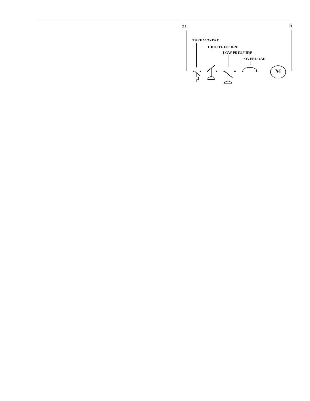
Most HVAC circuits contain more than one switch to
control a device. The example in Figure 6‐2 shows
that a thermostat, high‐pressure switch, low‐pressure
switch, and an overload (safety) must be closed to
complete the circuit to the motor. There are two
different ways of using a voltmeter to troubleshoot
this circuit. Each technician can adopt the method
that they are most comfortable with.
The sequence of troubleshooƟng should be: source,
load, path.
Lineal Searching
In a lineal search, start at the beginning of the circuit by tesƟng for voltage between L1 and N. Then
move the test lead from L1 to test for voltage at the thermostat, then the high‐pressure switch, low‐
pressure switch, overload, and finally, the motor terminals. By checking each side of the switched
components, open or faulty components or wiring can be found. This method locates the problem
component, but can be very Ɵme consuming.
Split Searching
A split search includes some advanced steps. Check for voltage at the load first. If there is voltage at
the load device, it is usually faulty and the rest of the circuit can be eliminated. If there is no voltage,
choose a point about midway through the circuit, starƟng at the low‐pressure switch. If there is
voltage available there, eliminate L1, the thermostat, and the high‐pressure switch as causes of the
problem. Then measure the remaining half of the circuit unƟl the problem is located. If no voltage
was found at the midpoint of the circuit (low‐pressure switch) the problem is before the test point.
Split searching can make troubleshooƟng complex circuits easier and less Ɵme consuming.
TROUBLESHOOTING USING A VOLTMETER
The majority of service problems are electrical problems, which usually cause mechanical problems.
Figure 6‐3 is a 230‐volt, single‐phase electrical schemaƟc of a typical commercial refrigeraƟon system.
The diagram includes a Ɵmer assembly with a defrost terminaƟon solenoid (DTS), evaporator fans,
defrost heaters, temperature acƟvated defrost terminaƟon/fan delay (DTFD) switch, low‐pressure
control (LPC), high‐pressure control (HPC), compressor contactor assembly, and compressor/potenƟal
relay assembly.
The system is drawn in refrigeraƟon mode and shows what voltages would be measured across
certain points of the schemaƟc if a voltmeter were used in troubleshooƟng. The diagram also shows
where Line 1 (L1) is in relaƟon to Line 2 (L2), for an easier understanding of the measured voltages.
NoƟce that anyƟme voltmeter probes see both L1 and L2, 230 volts is shown on the voltmeter.
AnyƟme voltmeter probes see the same line (L1 to L1 or L2 to L2,) 0 volts are read on the voltmeter
because there is no voltage difference between these measured points. So if the service technician
can find where L1 and L2 are when troubleshooƟng, the rest is easy to determine.
Fig. 6‐2: MulƟple switches/safeƟes