


 127 / 156

Electrical Theory & Applications for HVACR
Chapter 6: Troubleshooting
Page 115
but the boƩom switch is open. A voltmeter across terminals A and B of the top switch will read 0
volts because it is measuring a potenƟal difference between Line 1 and Line 1. Since the motor is
running, it is dropping 230 volts across the run winding (C and R terminals) of the PSC motor.
However, a voltmeter across terminals C and D of the boƩom switch will also read 0 volts. This
happens because Line 1 actually extends to the common terminal of the motor when it is running.
This would make terminals C and D of the boƩom switch both Line 1, and the voltage difference
between Line 1 and Line 1 is 0 volts. Actually, points A, B, C, and D are all Line 1.
Figure 6‐12 is a scenario where both an open switch and a closed switch read 0 volts. What
technicians must do when electrical troubleshooƟng is to ask themselves where Line 1 and Line 2 are,
not whether the switch is opened or closed. Measuring across the same line will always give 0 volts.
Measuring across Line 1 to Line 2 will always give the total circuit voltage, which in these examples
was 230 volts.
SYSTEMATIC TROUBLESHOOTING
Many service technicians are faced with troubleshooƟng refrigeraƟon and air condiƟoning systems on
a daily basis. Learning the most
efficient methods of troubleshooƟng
saves the service technician Ɵme as
well as the customer money. Good
systemaƟc troubleshooƟng techniques
are a win‐win situaƟon for both
customer and service technician.
Following is an example of a
systemaƟc troubleshooƟng method
incorporaƟng
a
symptoms/cause
method.
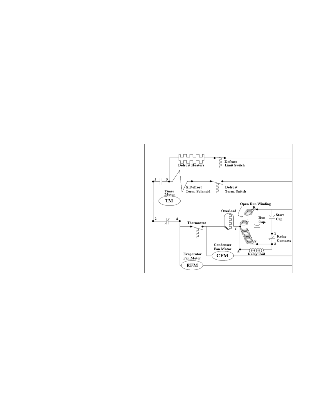
Figure 6‐13 illustrates an electrical
schemaƟc diagram showing a Ɵme
clock controlling a defrost circuit and a
refrigeraƟon circuit. NoƟce that in the
refrigeraƟon circuit, the compressor’s
run winding has been opened by a
motor overheaƟng problem. The
service call is a “no cooling” call for a
low‐temperature walk‐in cooler. Once the technician quickly looks the system over and listens for
any clues of what the problem may be, the electrical schemaƟc, if available, should be studied.
Understanding the logic or sequencing of the circuits before diving head‐over‐heals into the problem
is of utmost importance in systemaƟc troubleshooƟng.
In this scenario, an open run winding will cause certain symptoms not caused by other possible
system problems. For example, the technician listened to and examined the refrigeraƟon system and
then studied the electrical schemaƟc drawing. The service technician then lists the symptoms:
1.
Compressor motor hums and will not turn
2.
Compressor motor draws locked rotor amps (LRA)
Fig. 6‐13