


 129 / 156

Electrical Theory & Applications for HVACR
Chapter 6: Troubleshooting
Page 117
winding. Evaporator superheat, total superheat, and
condenser sub‐cooling, along with sucƟon pressure and
head pressure, must be taken for the system check. In
this case, the technician took a system check and found
the evaporator superheat to be very high at 40° and
the total superheat to be very high at 90°. Condenser
sub‐cooling was fine at 12°. Both sucƟon and head
pressure were low (see Figure 6‐14). The problem that
caused the overheaƟng was a faulty thermostaƟc
expansion valve. The valve would not open enough, and the enƟre low side of the system was being
starved. The compressor was a refrigerant‐cooled compressor. This caused the compressor to
overheat and cycle on its overload unƟl the run winding finally opened. Without this final system
check, the new compressor would surely fail in a short Ɵme.
VOLTMETER OR OHMMETER?
OŌen service technicians will encounter switches in series or parallel with electrical loads. Keeping
the electrical power on and using a voltmeter to voltage troubleshoot is the fastest and most reliable
method. However, there will be Ɵmes when a technician must switch to an ohmmeter and shut the
electrical power off in order to get to the root of the problem.
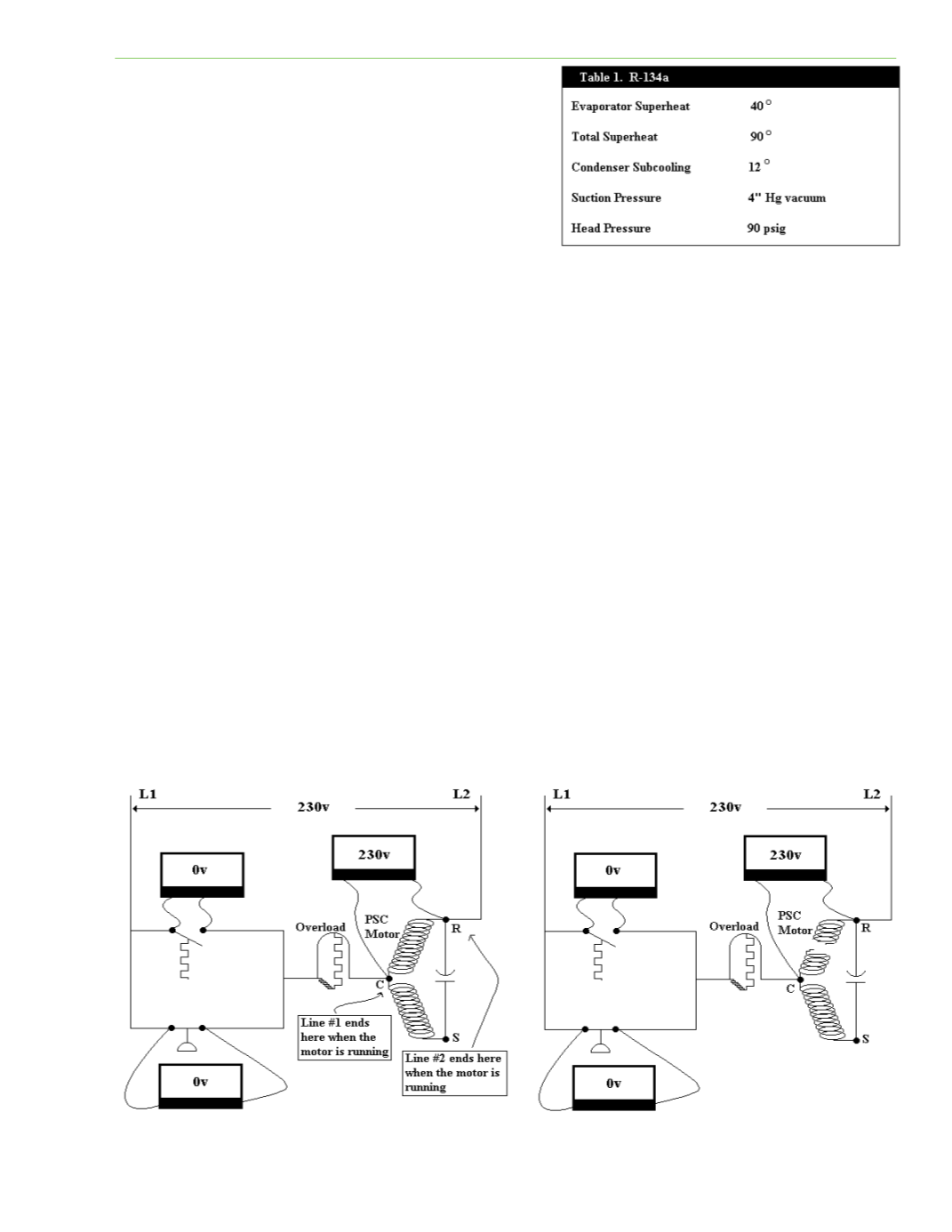
Figure 6‐15 shows an electric PSC motor in series with two switches that are in parallel with one
another. The voltage between points A and B (the open switch), in this case, would be zero volts
because the voltmeter would be measuring between Line 1 and Line 1. The voltage between points C
and D (the closed switch) would also be zero volts because of the voltmeter measuring between Line
1 and Line 1 again. Remember, the motor is running and dropping all of the 230 volts while it is
consuming power. A voltmeter across the R and S terminals of the PSC motor would read 230 volts
because the meter is measuring the voltage between Line 1 and Line 2, which is 230 volts.
Figure 6‐15 showed us that a voltmeter across the R and C terminals of the PSC motor would read 230
volts because it is measuring between Line 1 and Line 2. However, what would the voltage be
between R and C if the run winding between R and C opened, causing the motor to stall and draw
Fig. 6‐14
Fig. 6‐15
Fig. 6‐16