


 43 / 156

Electrical Theory & Applications for HVACR
Chapter 2: Circuits and Their Components
Page 31
condiƟoning). A three‐pole contactor has three sets of contacts and is used to control three‐phase
loads (for commercial and industrial).
It is normal for contacts to become piƩed and burned due to arcing when they open and close. Use
of a file or sandpaper to clean the contacts is not recommended; such
“cleaning” destroys contact surfaces and increases arcing. Large
amperage replacement contacts are usually available from local
suppliers.
The numbering system for contactors determines the direcƟon of
current flow through the contacts. It is standard policy for power
supply to enter at the top of the contacts and the load to be connected
to the boƩom. Line power (inlet) terminals are labeled L1, L2, and L3
and load (outlet) terminals are labeled T1, T2, and T3, according to the
number of poles.
CONTACTOR COIL BURN-OUT
The magneƟc coil is located inside the contactor but is not electrically connected to the main
contacts. Because the coil is a separate device, coil voltage can be different than voltage at the main
contacts. The coil has its own terminals for making electrical connecƟons, and replacement of the coil
is easy. Coils may be 24, 120, or 230 vac. And contacts may be rated 15 to 60 amperes. Because the
coil is electrically separate from the main contacts, it is common pracƟce to use lower voltage to
operate the coil. ResidenƟal systems generally use 24 vac. control system. Current in the control
circuit is safer and permits the use of standard switching devices and class‐two thermostat wire. A
step‐down transformer is used to obtain lower control circuit voltage.
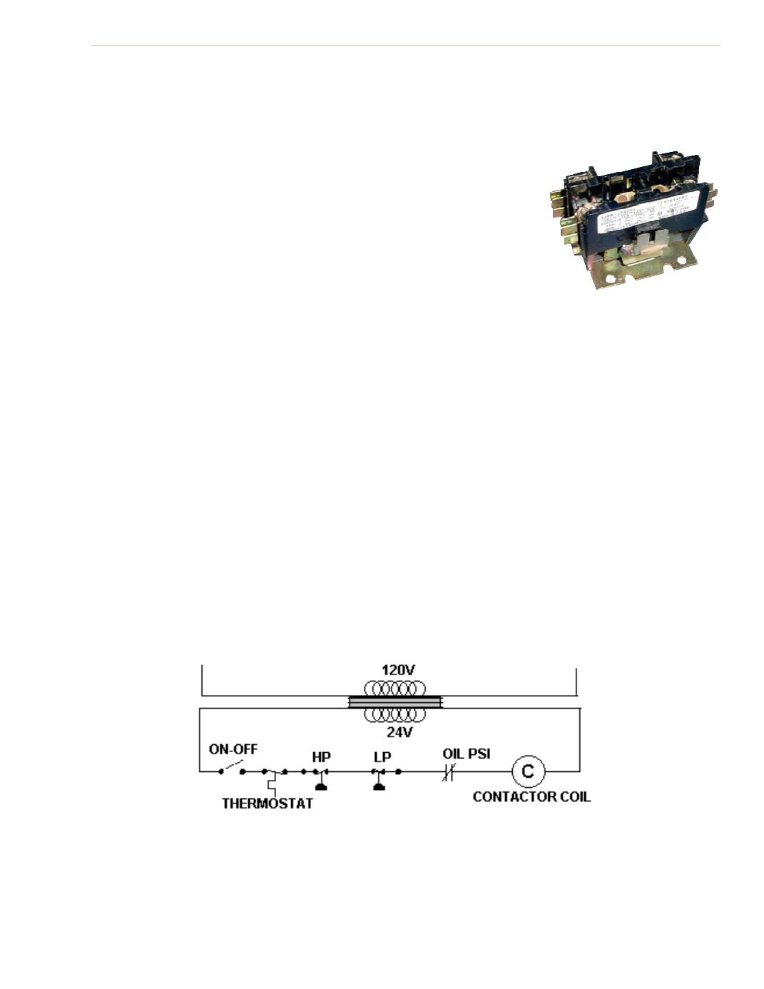
Any number of contacts and safety control switches can be located in the control circuit. Contacts for
these controls are connected in series with the coil and can include overloads, thermostats, pressure
controls, fuses, limit switches, flow controls, or oil pressure controls. All switches in the control circuit
in Figure 2‐26 must be closed before the coil can be energized. However, any switch can disconnect
power to the coil and stop the motor. Some safety controls have a manual reset, while others have
an automaƟc reset.
Fig. 2‐25: Single‐pole contactor
Fig. 2‐26: All control switches must be closed to energize the coil; any switch can open and
stop the motor