


 38 / 156

Page 26
Chapter 2: Circuits and Their Components
Electrical Theory & Applications for HVACR
LOADS AND SWITCHES
Manufacturers of electrical devices install the correct type
of resistance for the device to perform the correct amount
of energy conversion. It is important to connect these loads
to the designed voltage. When connecƟng a load to a
voltage source, a minimum of two conductors must be
used. A potenƟal difference (voltage) must exist between
the two wires. This power source is connected to each end
of the resistance. The potenƟal difference causes electrons
to flow through the resistance. Electrons flowing through
the resistance causes electrical energy to be converted to
another form of energy to provide useful work.
A load cannot operate unless the circuit provides a
complete pathway for electrons to flow into and out of the
load. Switches are always connected in series with a load
(one aŌer the other). More than one switch is oŌen used
to control and/or provide safety protecƟon.
To provide proper voltage supply, energy conversion
devices, are usually connected in parallel. A parallel circuit
is connected “from one side of the power supply to the
other”. The ulƟmate test of a parallel connecƟon is that the
device can be removed without effecƟng the operaƟon of
other devices. In parallel connecƟons, each device is
connected independently from all others.
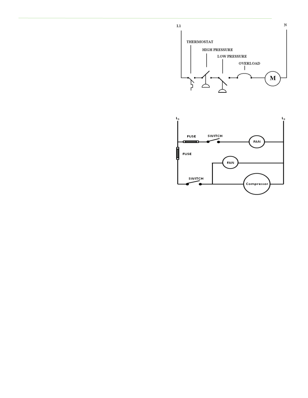
When more than one load is connected to a power source, switches are required to control the
individual loads. The switches are connected in series with the loads and each load is connected in
parallel to the power supply. SomeƟmes one switch may control more than one load. See Figure 2‐
16.
TRANSFORMERS
A chief advantage of alternaƟng current is that it can be generated at one voltage, transmiƩed at a
higher voltage, and then reduced to a lower voltage at the point of use. Transformers make it
possible to increase (step up) or decrease (step down) the voltage. When voltage is stepped up, the
required wire size for the secondary side is reduced, decreasing transmission cost. A transformer has
two windings: a primary (incoming voltage) and a secondary (outgoing voltage) winding. Voltage at
the secondary is determined by number of coils or wraps in the secondary winding versus number of
coils in the primary winding. Transformer primary terminals are normally labeled H1, H2, and H3, and
secondary terminals are tagged X1, X2, and X3. A neutral terminal is labeled X0.
Single‐phase transformers are rated by VA (volts x amps) at the secondary winding. Transformers
rated over 1,000 VA are usually rated KVA, with K represenƟng 1,000. An overloaded or undersized
transformer will burn out because the secondary coil cannot carry the required current. The
Fig. 2‐15: MulƟple switches safeƟes
Fig. 2‐16: Switches and fuses connected in
series with loads