


 40 / 156

Page 28
Chapter 2: Circuits and Their Components
Electrical Theory & Applications for HVACR
LOW-VOLTAGE TRANSFORMERS
Step‐down transformers have less windings in the secondary than the primary, which makes
resistance less in the secondary. A 240‐volt primary has a raƟo of 10:1 windings for a 24‐volt
secondary; a 120‐ to 24‐volt has a raƟo of 5:1 for 24 volts.
Twenty‐four‐volt control transformers used in HVAC equipment have a volt‐amp raƟng between 16
and 50. To find the amperage capacity of a low‐voltage transformer, divide the volt/amp (VA) raƟng
by the secondary voltage output.
Example:
RaƟng: 24 volts/40 VA
40 VA ÷ 24 volts =
1.7 amps maximum secondary load
Most transformers have an internal fuse to prevent the transformer from high‐amperage burn‐out.
Some manufacturers install a ±2 amp Ɵme‐delayed fuse in the secondary side for addiƟonal
protecƟon.
Some equipment has two transformers: one in the indoor unit and one in the outdoor system.
Depending on equipment and type of controls used, transformers
may need to be wired in phase to each other or in phase to ground.
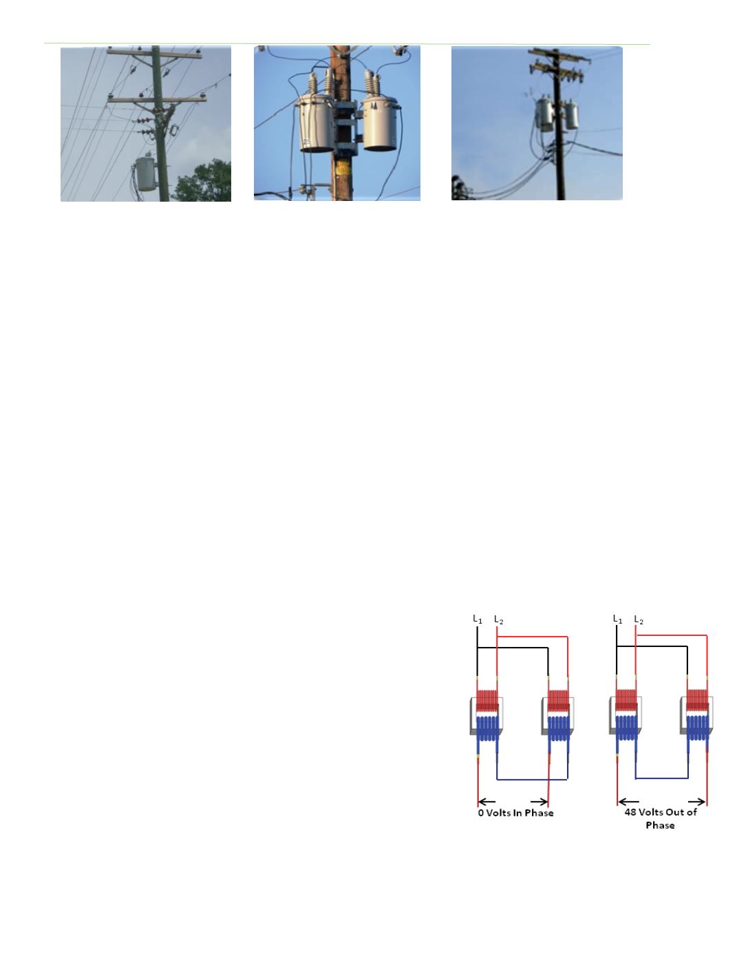
To properly wire two low‐voltage transformers in phase, the primary
and secondary windings of both transformers must be connected so
that current flow is in the same direcƟon in each transformer. L1
and L2 must be connected as shown in Figure 2‐20(a) on the
transformer, L1 to L1 and L2 to L2.
The secondary windings of both transformers must be connected in
parallel and in phase. To check the phasing connect one 24‐volt lead
from each transformer together. With a voltmeter, measure the
voltage between the two other 24‐volt connecƟons. If in phase, the
voltmeter will indicate 0 volts; if out of phase, the voltmeter will
indicate 48 volts. If the measurement is 48 volts, the wires on either
the primary or secondary side of the transformer must be reversed.
Fig. 2‐19(b): 230/120 V
three‐phase with high‐leg
Fig. 2‐19(c): 230/120 V three‐
phase
Fig. 2‐19(a): Single‐phase
230/120 V
Fig. 2‐20(a): Transformer phasing