


 42 / 156

Page 30
Chapter 2: Circuits and Their Components
Electrical Theory & Applications for HVACR
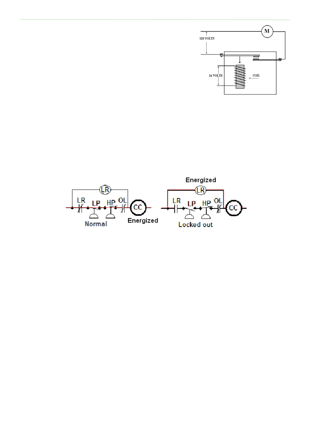
open or close. The electrical circuit to the relay coil is enƟrely
separate from the circuit through the relay contact. The coil
voltage may be 24 volts and the circuit through the relay
contacts may be 120 volts. Thus, low voltage is used to control
a switch that controls a high‐voltage load. See Figure 2‐23.
Relays oŌen contain more than one set of contacts or switches.
Relay contacts are always shown as normally open (NO) or
normally closed (NC) with the coil in the de‐energized posiƟon.
Energizing the coil causes the contacts to change posiƟon. The
relay contacts have low current raƟngs, with a maximum of 10
amps being considered normal. Current flow in the coil circuit
is very low, oŌen less than 1/4 ampere. A 24‐volt control
circuit is safer for personnel, permits the use of smaller wire, and causes less arcing at the switch.
A lock‐out relay is a relay with approximately 75 percent more resistance than the coil of the control
it locks out. This difference allows for the proper voltage drop so that one coil will energize and the
other will not. It is wired in a circuit as shown in Figure 2‐24.
SEQUENCER
If mulƟple loads are energized at the same Ɵme, an overwhelming current surge or load is placed on
the power supply. When this occurs in a residenƟal home, lights may dim or flicker; in a commercial
building, electrical demand for purchased electrical energy will be billed at a high‐demand rate for
the enƟre month.
Sequencers are Ɵme‐delay relays that stage loads on and off and are commonly found on electric
heaƟng systems connected to heaƟng elements.
CONTACTORS
A contactor is an electrical switching device that operates much like a relay. However, the contactor
has heavy‐duty contacts for controlling larger loads. These contacts are normally open (NO) and
controlled by a magneƟc coil. When the coil is energized, the contacts close. Contacts are used to
open or close a circuit between the main power supply and the load and are rated according to the
maximum amperage flow through the contacts for a specific voltage. A two‐pole contactor has two
separate contacts and is used to control 240‐volt single‐phase circuits (for residenƟal air
Fig. 2‐23: The coil circuit is separate
from the motor circuit
Fig. 2‐24: Lock‐out relay circuit