


 37 / 156

Electrical Theory & Applications for HVACR
Chapter 2: Circuits and Their Components
Page 25
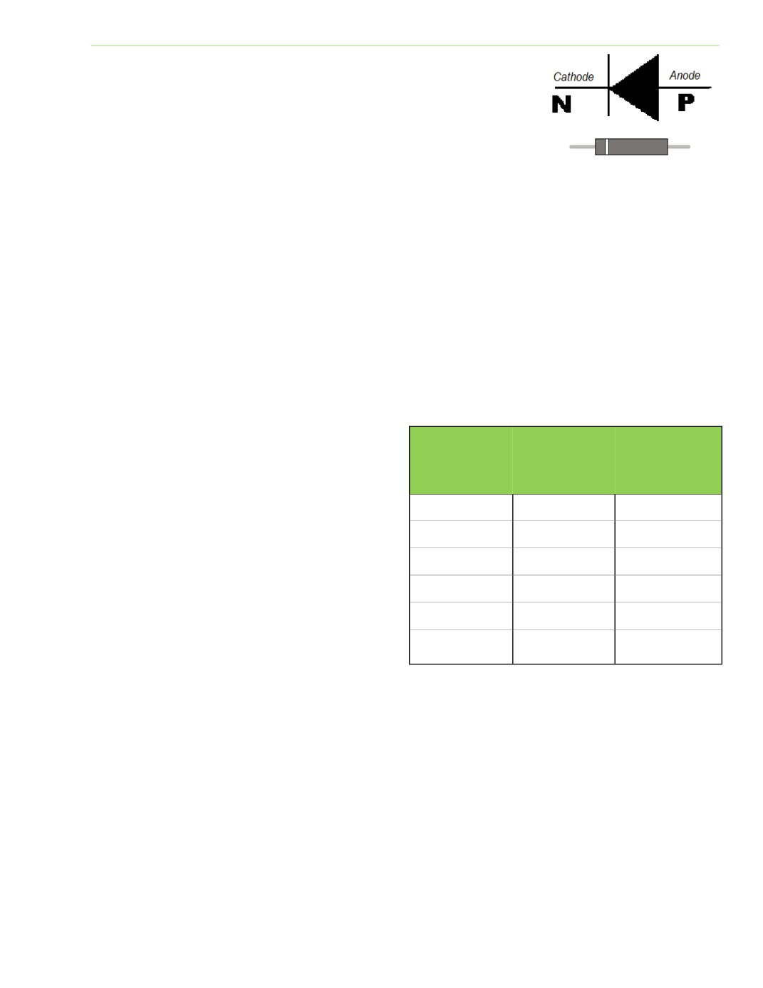
An electrical check valve can be created by sandwiching pieces of N‐
Type and P‐Type material together. Electrons can flow into the N‐type
material and out of the P‐Type material, but electrons aƩempƟng to
enter the P‐Type material are blocked and no current flows. This
simple solid state device is called a diode. A diode is represented in
electrical schemaƟcs by the symbol in Figure 2‐13.
CIRCUIT PROTECTION
Overcurrent occurs when excess current is flowing through a wire.
This causes the wire to become hot and presents a serious hazard. Overcurrent can be caused by a
variety of electrical problems such as loose connecƟons, ground fault, short circuit, defecƟve
resistance, or too many loads. An overload describes an overcurrent (between two and ten Ɵmes
the rated current.) A ground fault describes an overcurrent which runs to ground and may be
hundreds of Ɵmes the rated current. A ground fault is VERY dangerous.
Fuses and circuit breakers protect a circuit against overcurrent. The amperage raƟng of a fuse must
not be greater than the ampacity of the wires being protected. Fuses and circuit breakers are used
to detect excessive load current and open the circuit before danger arises. Examine the fuse clamp
holder for discoloraƟon or loose connecƟons; this indicates an overheated connecƟon. It is standard
pracƟce to locate fuses in the main power supply
and in each branch circuit. A blown fuse in a
branch circuit helps confine the problem to a
specific area. Fuses, overloads, and circuit
breakers protect wires and equipment, not
people.
The amperage and voltage raƟng of a cartridge
fuse determines the physical size of the fuse.
Fuse holding devices are sized according to the
same procedure. This helps prevent oversizing
fuses on circuits designed for a certain maximum
amperage. Figure 2‐14 illustrates fuse
dimensions in inches according to voltage, and
amperage raƟngs of the fuses.
Cartridge fuses are available as ordinary fuses (one‐Ɵme blow) or dual‐element. Dual‐element, or Ɵme‐
delay, fuses permit an overload of short duraƟon, but blow instantly if a short circuit occurs. Time‐delay
fuses are necessary when fusing circuits for electric motors. Screw‐in or Ɵme‐delay fuses are sized up to 30
amperes. If the view port on a screw‐in fuse is blackened or the skinny part of the element is burned, the
fuse has experienced extreme overload. If a port reveals a collapsed spring inside, the fuse has experienced
a slight overload. Round cartridge fuses are used up to 60 amperes and knife‐blade contacts are used for
fuses over 60 amperes. It is important that fuse ends make Ɵght contact in the fuse holder. Loose
connecƟons or high air temperatures around a fuse reduce the amperage raƟng and cause needless
shutdowns. Remember never to pull a fuse under a load, and always use a fuse puller to remove cartridge
fuses.
Fig. 2‐13: SchemaƟc symbol for
diode
AMPERAGE
RANGE
250 V
FUSE LENGTH
(INCHES)
600 V
FUSE LENGTH
(INCHES)
1/10 to 30
2
5
35 to 60
3
5 1/2
70 to 100
5 7/8
7 7/8
110 to 200
7 1/8
9 5/8
225 to 400
8 5/8
11 5/8
450 to 600
10 3/8
13 3/8
Fig. 2‐14: Amperage and voltage determine fuse size