


 34 / 156

Page 22
Chapter 2: Circuits and Their Components
Electrical Theory & Applications for HVACR
Many electrical loads, generally commercial, are designed for connecƟon to all three hot wires; these
are called three‐phase loads. The normal color code for these wires is black or red, but they can be
any color except white or green. The leƩer “L” for “line” is used to help idenƟfy the three phases (L1,
L2, L3).
SINGLE-PHASE CIRCUITS
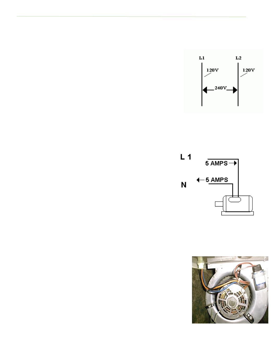
Some loads are designed to operate with just two hot wires from a
three‐phase system. These are called single‐phase loads, not two‐
phase. (The term “two‐phase” refers to an old system sƟll used in a
few remote areas.) Higher voltage is obtained by using two wires, from
a three‐phase system, that alternate from posiƟve to negaƟve. This
push‐pull effect can be obtained with any two phases. See Figure 2‐5.
The allowable voltage variance in a single‐phase circuit is ten percent.
THE NEUTRAL WIRE
Earth is an excellent conductor of electricity, and damp soil is a beƩer conductor than dry soil. The
earth is always at zero potenƟal (no voltage) and can be used to complete an electrical circuit. Many
electrical devices operate with one hot wire from a three‐phase system and another wire called the
neutral. This method is also called single‐phase, and involves lower voltage. A potenƟal difference
exists because the hot wire has voltage and polarity, but the
neutral wire is connected to the earth, or grounded, which has
zero voltage.
While the hot conductor usually has black insulaƟon, it can be
another color (except white or green) for ease of idenƟficaƟon.
The neutral wire has white or gray insulaƟon and is connected to
a solid copper rod driven eight feet into the ground. This copper
rod is called a “grounding electrode.” This grounded neutral wire
provides a pathway for electrons traveling to and from the Earth,
and has zero voltage. The neutral wire is a current carrying
conductor, but has no voltage to ground. A potenƟal difference
exists between the neutral wire (no voltage) and the black wire
having 120 volts. See Figure 2‐6.
THE SAFETY GROUND WIRE
The equipment grounding conductor is another wire added for safety
purposes. This is called the safety ground and is required by the NaƟonal
Electric Code on all new electrical systems. The color code for this wire is
green or bare copper (not insulated). The safety ground, or chassis ground,
connects to the same terminal as the neutral wire once at the service
panel. The neutral wire normally carries current. The safety ground only
carries current in the event of a short circuit. This conductor serves strictly
as a safety valve when a ground fault occurs in the electrical equipment.
The safety ground wire is connected to the frame of a motor or appliance
and provides an alternate pathway for electrons to travel to ground and not
through someone’s body. Many commercial and industrial applicaƟons
Fig. 2‐5: 240‐Volt, 1Ø System
Fig. 2‐6: Amperage flowing in the hot
wire also flows in the neutral wire
Fig. 2‐7: Motor safety ground
TO
GROUND