


 32 / 156

Page 20
Chapter 2: Circuits and Their Components
Electrical Theory & Applications for HVACR
Remember, voltage (E) remains constant and resistance total is always less than the least resistance in
the circuit.
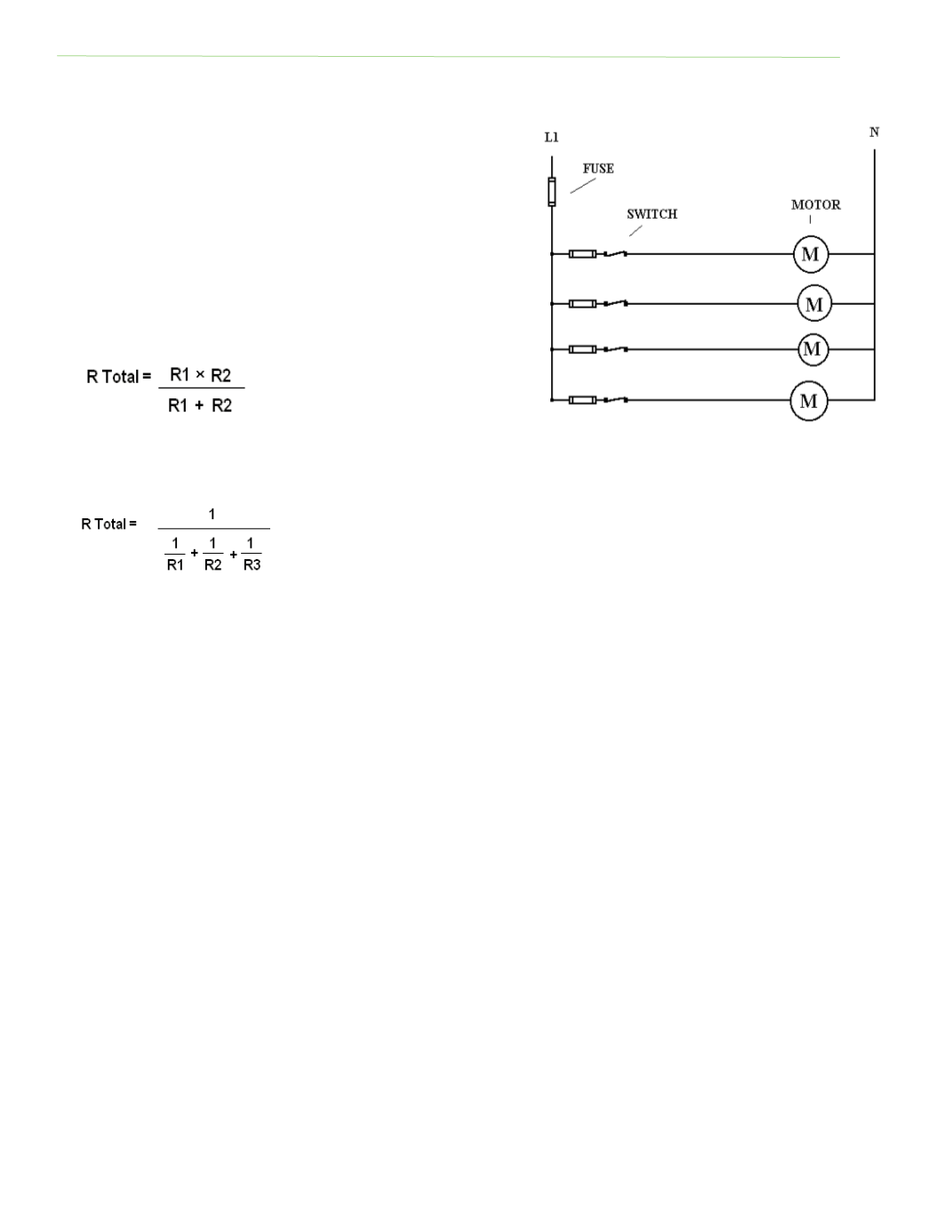
Total Resistance in a Parallel Circuit
Since a parallel circuit has more than one path for current
flow, adding addiƟonal paths (loads) will decrease the total
resistance in the circuit. The total resistance is always less
than the smallest resistance in the circuit.
Formulas to calculate total resistance in a parallel circuit:
For two resistors:
For three or more resistors:
Parallel Circuit Laws
1. More than one path for current to flow.
2. Voltage remains constant throughout the circuit.
3. Total current is equal to sum of all branch currents.
4. Total resistance is always less than the least resistor in the circuit.
COMBINATION SERIES/PARALLEL CIRCUITS
Voltage, resistance, amperage, and power in a complex circuit such as a combinaƟon series/parallel
circuit vary in each secƟon of the circuit. To determine these values, the parallel and series secƟons
of the circuit must be calculated separately before finding circuit total. In Figure 2‐3, the parallel
secƟon as shown in the circle must be calculated before adding it to the series secƟon of the circuit.
THREE-PHASE CIRCUITS
A power plant generator rotates a magneƟc field within three different conducƟng loops at the same
Ɵme. This is called poly‐phase generaƟon, and it is much like having three different power plants.
The three conducƟng loops are spaced exactly 120 degrees apart and are called phases (Ø) or legs.
While one phase is magneƟcally posiƟve, another phase is negaƟve and the other is at zero. These
three phases take turns changing polarity from posiƟve to negaƟve to zero at a rate of 7,200 Ɵmes
per minute. This three‐way posiƟoning is conƟnuous as each loop rotates inside the generator,
producing alternaƟng current in each of the three phases that are out‐of‐step or out of phase with
each other. The voltage variance between phases should not exceed two percent.
Fig. 2‐2: Parallel circuit