


 68 / 156

Page 56
Chapter 3: Motors
Electrical Theory & Applications for HVACR
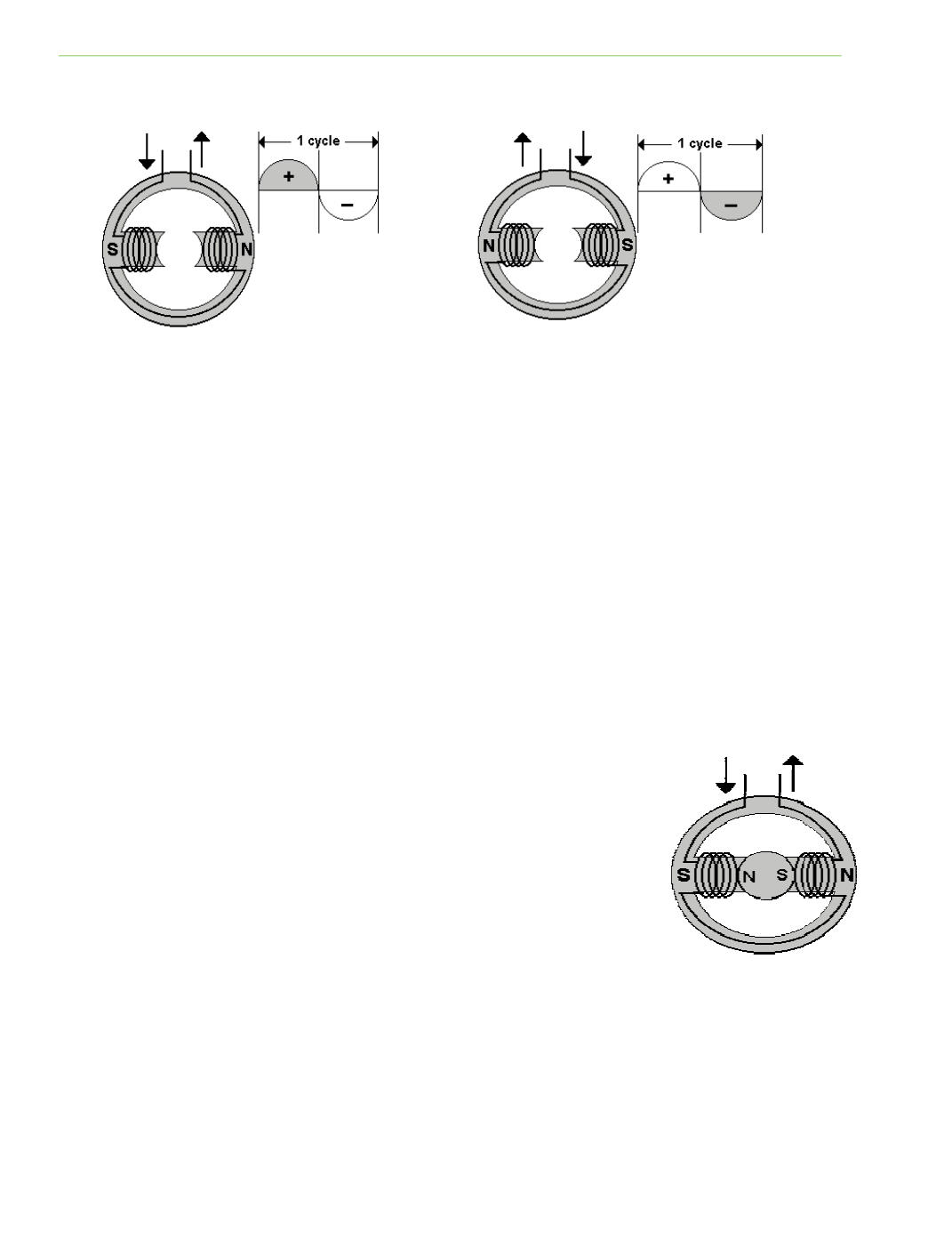
reverses, the polarity of each stator changes. Thus, the polarity of stator electromagnets
automaƟcally changes with alternaƟng current flow.
STATORS
Motors have staƟonary coils of copper wire called main windings, which are carefully wrapped
around layers of soŌ iron called poles. These magneƟc poles consist of coils and laminated cores and
are permanently mounted inside of the motor shell. A minimum of two poles, one north and one
south, is required. Each pole is located exactly 180 degrees around the circle. This arrangement of
magneƟc poles is called the stator.
The size (AWG) of copper wire used and the number of wraps in the coil determines the amount of
resistance in the coil. The coil resistance, reactance, and load determine the amount of current
flowing through the coil. Current flow determines the strength of the pole’s magneƟc field.
ROTORS
One common type of rotor is called a squirrel cage. Instead of wires, copper bars are inserted into
slots in the surface of the core. The ends of these copper bars are joined together, forming a series of
closed loops arranged to form what looks like a cage.
The fields created by the stator electromagnets cut across the closed loops in
the rotor and large currents are induced in the rotor loops. These induced
currents create a magneƟc field in the rotor with the opposite polarity of the
stator electromagnet. Because opposite magneƟc poles aƩract, the rotor is
locked into a fixed posiƟon. The aƩracƟon of unlike poles results in a
condiƟon called locked rotor, meaning the rotor cannot turn. If the rotor is
spun, it will conƟnue to spin due to the alternaƟng polarity of the stator
poles.
This push‐pull acƟon is conƟnuous as the poles reverse polarity and the rotor
tries to catch up with the changing polarity.
MOTOR SPEED
Motor speed is determined by the number of stator poles. Rotor speed is measured in revoluƟons
per minute (RPM). Synchronous speed is determined by dividing 7,200; the number of alternaƟons
(changes from posiƟve to negaƟve) per minute in a 60 Hz circuit by the number of stator poles . A
Fig. 3‐3: Coils wrapped on stator poles
Fig. 3‐4: Polarity changes 120 Ɵmes per second
Fig. 3‐5: Rotor polarity is
opposite of stator poles