


 71 / 156

Electrical Theory & Applications for HVACR
Chapter 3: Motors
Page 59
When recording rotaƟon direcƟon, always indicate which end of the motor is being viewed. If the
shaŌ is turning to the right, rotaƟon is clockwise (CW). If the shaŌ is turning to the leŌ, rotaƟon is
counter clockwise (CCW). Not all motors have wiring connecƟons that allow the motor to be reversed
in the field.
DISCONNECTING THE START WINDING
The only purpose of the start winding in a split‐phase motor is to start the motor. Once the motor
has started, the start winding must be removed from the circuit or it will burn out. FracƟonal
horsepower (Hp) motors use a centrifugal switch or relay for disconnecƟng the start winding aŌer
start‐up. Open motors have a centrifugal switch inside the motor that is connected in series with the
start winding.
Motors of less than one horsepower are called
fracƟonal horsepower motors. For example, 1/2 hp
and 1/4 hp are fracƟonal horsepower motors.
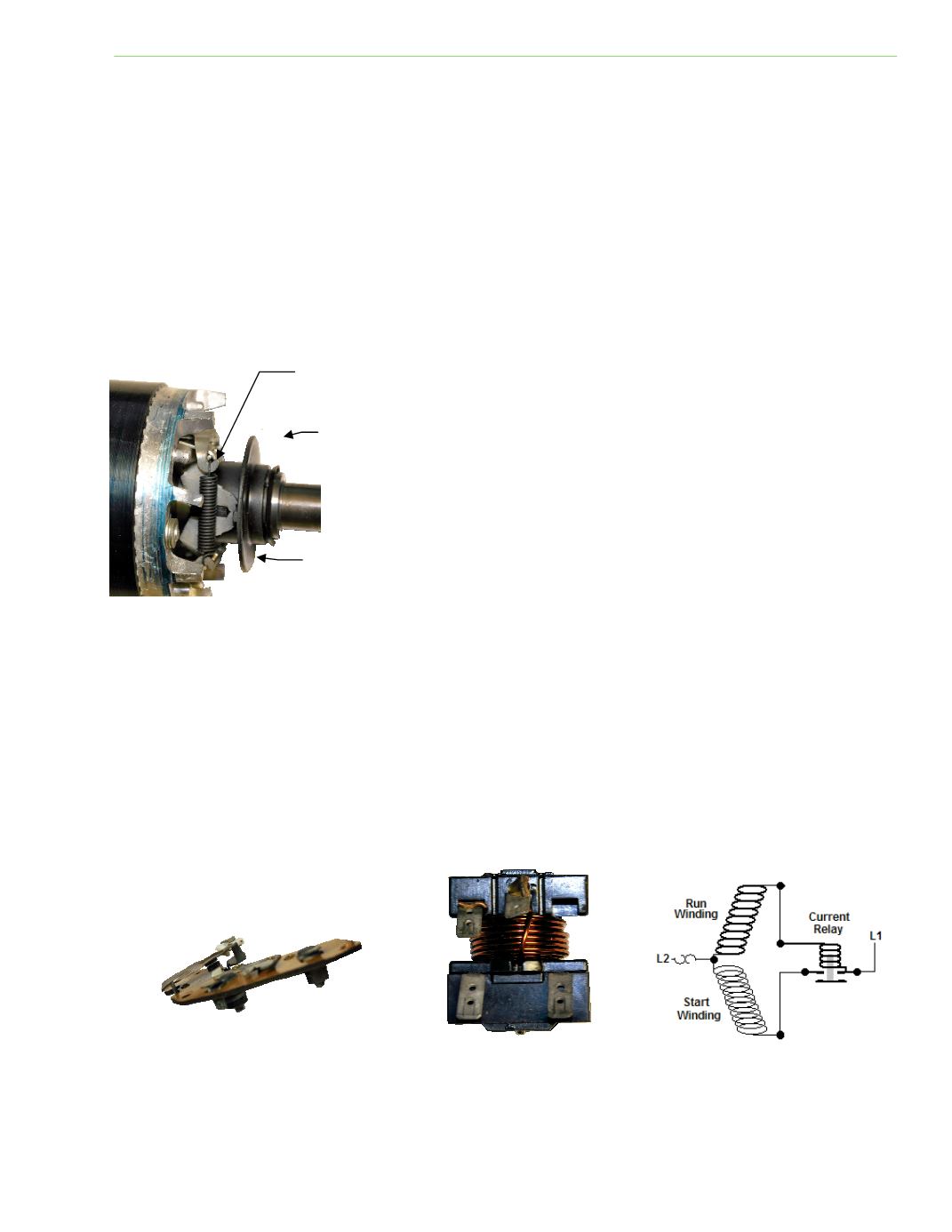
The contacts on the centrifugal switch in Figure 3‐10
are closed when the motor is not running. When the
motor achieves 75 percent speed, enough centrifugal
force is produced to make a pair of weights swing
outward and open the switch. When the motor stops,
springs pull the weights back and the switch is closed
for the next start‐up. Failure of the centrifugal switch
to open permits the start winding to remain in the
circuit, resulƟng in high amperage. In this case, the
motor overload should stop the motor.
A current relay or posiƟve temperature thermistor (PTC) can be used on fracƟonal horsepower, open
motors, or sealed refrigerant compressors to disconnect the start winding. The current relay coil
produces a magneƟc field from the high starƟng current, liŌing the contacts closed and energizing the
start winding. AŌer the rotor starts turning, current decreases and the contacts open.
Fig. 3‐11: Centrifugal switch contacts
Fig. 3‐12: Current relay
Fig. 3‐10: Centrifugal switch
MOVABLE COLLAR
CONTACT POINTS
CENTRIFUGAL WEIGHTS
Fig. 3‐13: Current relay wiring