


 75 / 156

Electrical Theory & Applications for HVACR
Chapter 3: Motors
Page 63
SHADED POLE AND PSC MOTOR SPEEDS
InducƟon fracƟonal horsepower motor speed is determined by the number of run windings added to
the stator poles or the number of poles used. A mulƟ‐speed motor has several external taps (wires)
for selecƟon of motor speed. The desired motor speed tap is connected to the power source. The
supply voltage (L1 & L2) must not be connected between two speed taps. The low resistance
between speed taps will cause the motor to burn out as soon as power is applied.
CAPACITORS
Capacitors are oŌen used to improve the operaƟng characterisƟcs of single‐phase motors. A
capacitor is an electrical device that stores and discharges electrical energy, causing more of a phase
shiŌ than a shading coil and winding does. Capacitors increase and decrease the magneƟc field
produced by the motor start winding. There are two different types of capacitors: start and run. All
start and run capacitors are wired in series with start windings and are in parallel with each other on
start‐up.
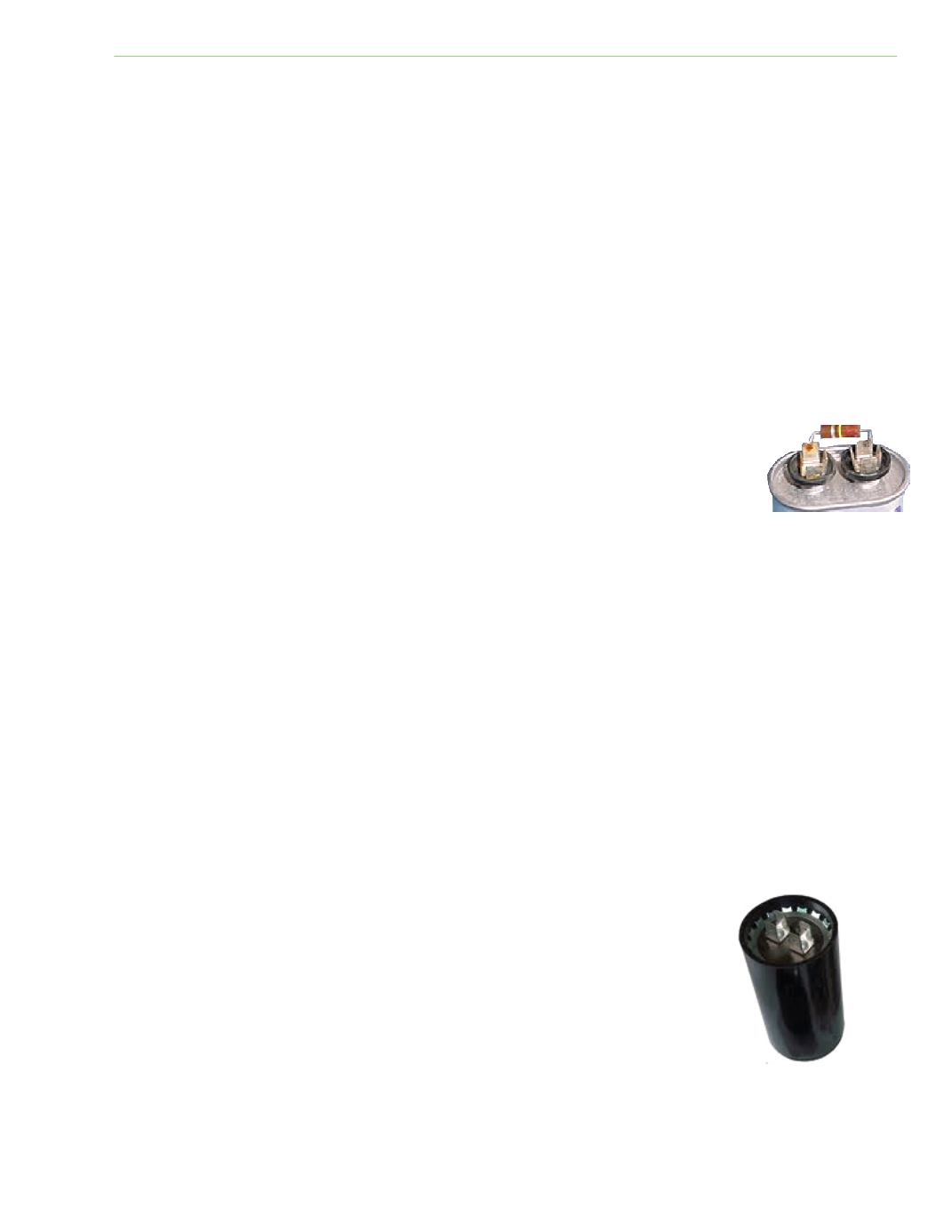
Many capacitors have a bleed resistor soldered or connected to the terminals to
safely discharge the capacitor each Ɵme the circuit opens. The purpose of the
resistor is to reduce the severity of arcing that occurs at the relay contacts and
reduce the possibility of a technician being shocked when removing a capacitor
with a bleed resistor from the circuit.
START CAPACITORS
A start capacitor is connected in series with a motor start winding and switch. The applied voltage
forces one side of the capacitor to fill with excess electrons while the other side discharges its excess
electrons into the start winding. When the current alternates, the empty side again fills up while the
other side discharges. The electrons rush into and out of each side of the capacitor, according to the
alternaƟng current. When one side is full, the other is empty. One side of the start capacitor
discharges excess electrons into the start winding. This increases current flow in the start winding
and increases the strength of the magneƟc field, providing beƩer starƟng torque. The start capacitor
is not designed to stay in the circuit aŌer the motor starts. It is typically energized for between .75
and one second and should never exceed four seconds. Start capacitors are easily damaged and can
tolerate about twenty starts per hour without overheaƟng. Start capacitors are usually constructed
with a plasƟc bakelite case.
Replacement capacitors should have the same microfarad and voltage
raƟng as the one being replaced. In an emergency situaƟon, a replacement
start capacitor up to 20 percent over capacity may be used as a temporary
repair. Never install a capacitor that is under capacity.
Fig 3‐21: Bleed resistor
Fig. 3‐22: Start capacitor