


 80 / 156

Page 68
Chapter 3: Motors
Electrical Theory & Applications for HVACR
The resistance of all three windings in a three‐phase motor is the same. For single voltage motors,
only one end of each winding is brought outside the motor for connecƟon to the power source. The
other end of each motor winding is factory connected inside the motor.
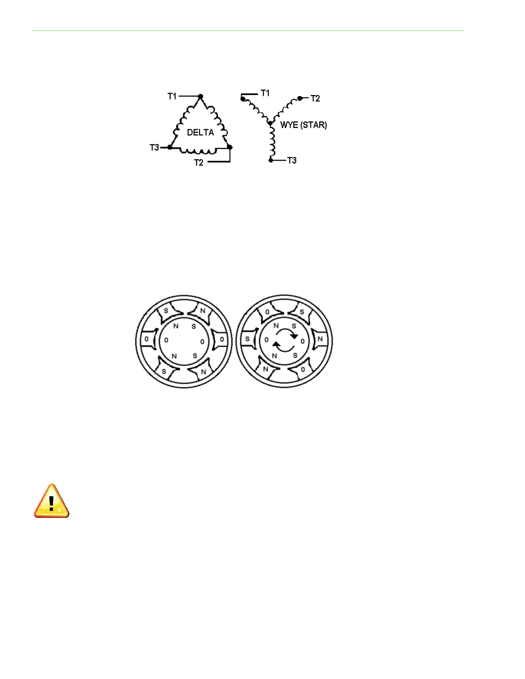
With three‐phase alternaƟng current, the three power supply wires are 120 degrees out of phase and
take turns changing polarity from north to south. When one pole is north, the second is rising and the
third is dropping. This changing of polarity in the supply wires produces a strong rotaƟng magneƟc
field in the stator poles that are out of step with each other. The alternaƟng current produces
different levels of magneƟsm in the set of stator poles producing the rotaƟng push‐pull effect on the
rotor. In Fig 3‐31 the six physical poles are separated by 60 electrical degrees.
CHANGING THE ROTATION OF A THREE-PHASE MOTOR
DirecƟon of rotaƟon is determined by the direcƟon of the rotaƟng field. Reversing rotaƟon on a three
‐phase motor is done by interchanging any two supply wires. This simple procedure causes the
magneƟc field to rotate in the opposite direcƟon.
Improper rotaƟon can be devastaƟng to equipment and personal safety. If necessary,
disconnect equipment before checking proper motor rotaƟon.
CHECKING RESISTANCE OF WINDINGS
The motor windings on a three‐phase motor can be checked with an ohmmeter. The motor must be
disconnected from the circuit and the measurements obtained from one motor lead to another. If a
resistance measurement of zero is obtained, the winding is shorted. If a measurement is obtained
from any motor lead to ground, the winding is grounded. A measurement of infinite resistance
indicates that the winding is open. In each of these cases, the motor must be re‐wound or replaced.
Fig. 3‐30: SchemaƟc symbols for Delta and Wye three‐phase
Fig. 3‐31: Stator polarity produces a push‐pull effect on the rotor