


 77 / 156

Electrical Theory & Applications for HVACR
Chapter 3: Motors
Page 65
CURRENT RELAY
The current relay is used on motors normally rated one horse power or less
(See fig. 3‐15) . The coil of a current relay is made of 18‐ to 14‐gauge copper
wire for low resistance (usually less than one ohm). The main terminals of a
current relay are L, M, and S, with L connecƟng to line, M connecƟng to run
winding, and S connecƟng to the start winding or start capacitor. Since the
coil is connected in series with the run winding, it must have a very low
voltage drop and be able to carry the amperage draw of the motor. The
contacts are normally open (NO) and the sequence of operaƟon is:
Motor off
—contacts open
Motor energized
—contacts closed
Motor starƟng amperage drops
—contacts open
StarƟng current (LRA) through the coil creates a magneƟc field that pulls the solenoid up to close the
contacts in series with the start winding or start capacitor. As the motor comes up to speed,
amperage decreases, magneƟc force reduces, and gravity pulls the solenoid down to open the start
contacts.
To check the contacts, an ohmmeter can be connected to the L and S terminals. There should be
conƟnuity with the relay turned upside down. Due to movement and the way contacts close, the
relay should be turned over three or four Ɵmes and checked each Ɵme. Usually, a coil failure is easily
detected by a visual inspecƟon for a burnt spot and a check for conƟnuity between L and M.
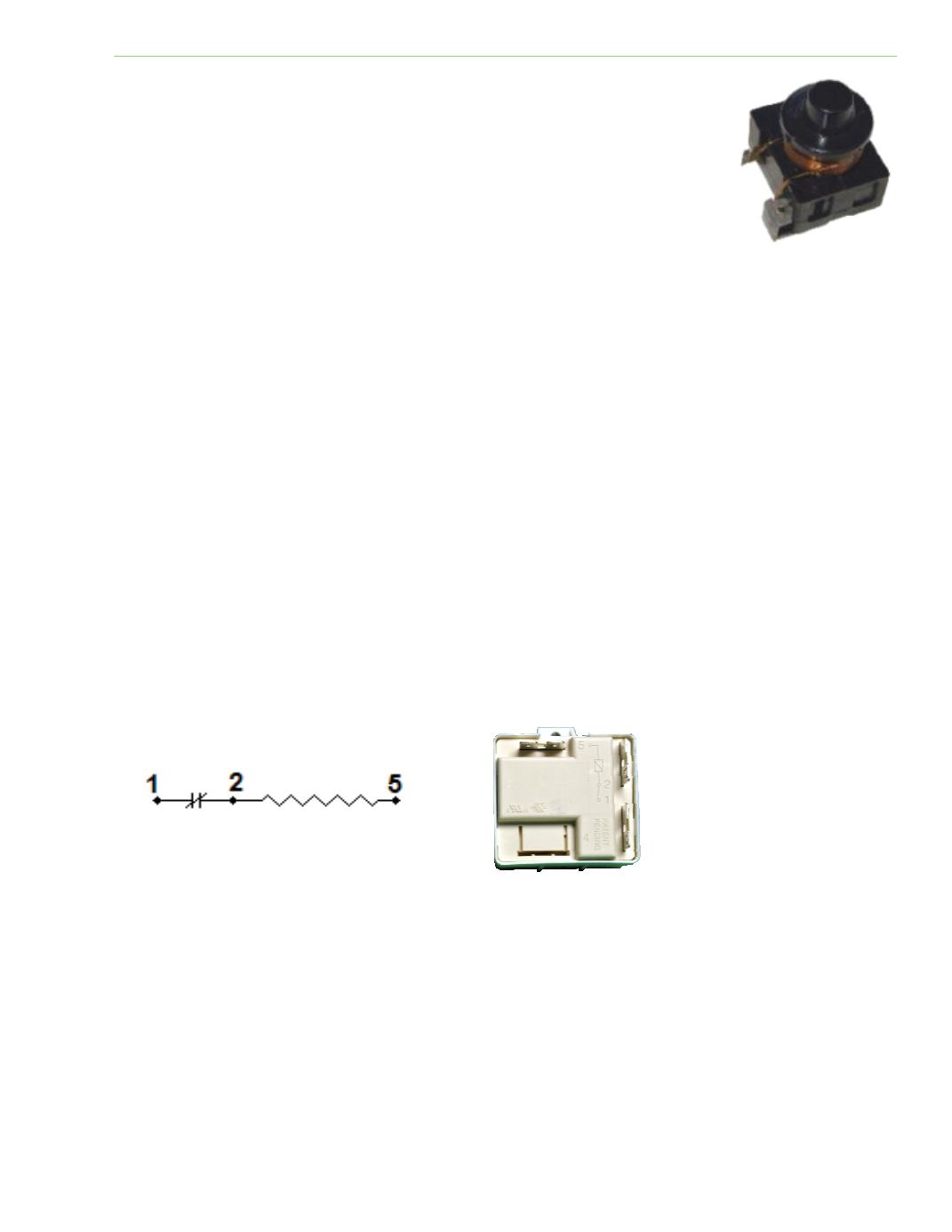
POTENTIAL RELAY
A potenƟal or voltage relay has a coil and set of normally closed contacts wired in series. The main
terminals of a potenƟal relay are 1, 2, and 5. Terminal 1 connects to the start capacitor, terminal 2 to
the start winding at the run capacitor, and terminal 5 to the common of the compressor (See fig. 3‐
17). Note: The leg of line voltage feeding a run winding must also feed the capacitors.
A relay coil is idenƟfied as terminals 2 and 5 and has a very high resistance. The normally closed (NC)
contact is idenƟfied as terminals 2 and 1. The relay coil is wired parallel to the start winding.
Contacts are wired in series with the start capacitor and the line feeding the run winding. The relay
coil is energized by the counter (back) electromoƟve force from the start winding. Voltage induced in
the start winding is greater than applied line voltage. Because the start winding has a higher
resistance and more turns than the run winding, it acts like a step‐up transformer. As the rotor
begins to turn, magneƟc lines of flux cut through the windings at a faster rate, causing the back EMF
to increase with the rotor speed. As the compressor gets to 75 percent operaƟng speed, voltage
becomes high enough to energize the potenƟal relay coil and the contact opens. The relay has three
raƟngs: conƟnuous coil voltage, contact pick‐up voltage (open), and contact drop‐out voltage (close).
Fig. 3‐24: Current relay
Fig 3‐25: PotenƟal relay wiring
Fig. 3‐26: PotenƟal relay
Coil