


 81 / 156

Electrical Theory & Applications for HVACR
Chapter 3: Motors
Page 69
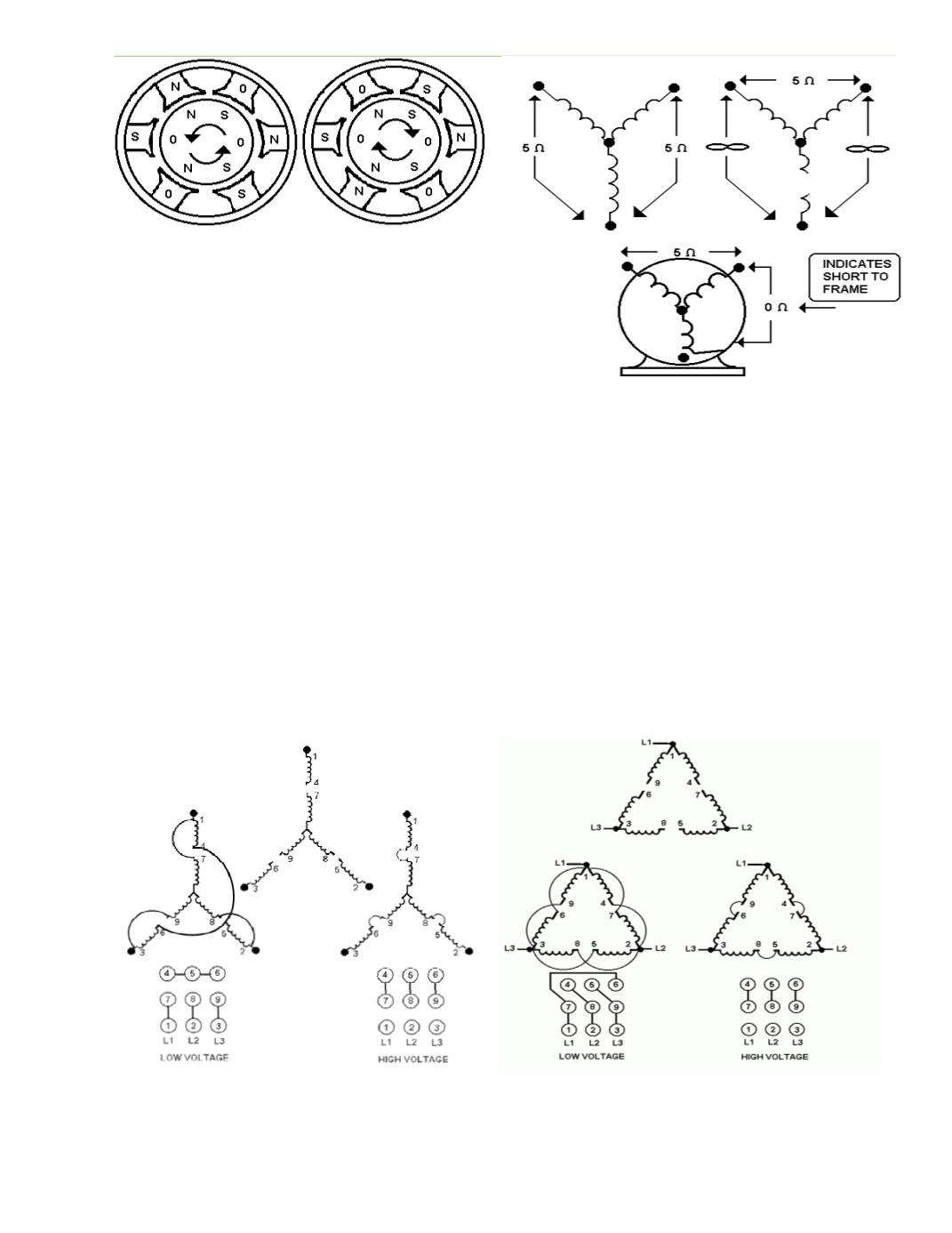
The resistance measurement on three‐phase
motors windings will vary from less than one
ohm to 50 ohms, depending on motor size. The
larger the motor, the lower the resistance.
Each winding has the same resistance, except
for dual‐voltage windings. A dual‐voltage motor
has its main windings split into six windings of equal resistance.
DUAL-VOLTAGE THREE-PHASE MOTORS
Many three‐phase motors are designed for connecƟon to either of two different voltages: 240 or 440.
These are called dual‐voltage motors. Instead of having just three external wires to connect, these
motors have nine or twelve. The wires are tagged and numbered for easy idenƟficaƟon. NEVER
remove these numbers.
Regardless of which voltage is being connected, all wires must be connected properly. When
connected to the lower voltage, the windings are connected in parallel; when connected to the higher
voltage, they are connected in series. The three power supply wires are ALWAYS connected to motor
numbers T1, T2, and T3.
Fig. 3‐32: Changing any two supply wires changes
the rotaƟon of the rotor
Fig. 3‐33: An ohmmeter is used to check motor windings
Fig. 3‐35: Low‐ and high‐voltage connecƟons for a
Delta‐connected motor
Fig. 3‐34: Low‐ and high‐voltage connecƟons for a
WYE (Star)‐connected motor